Rockwell Automation 8520 9/Series CNC Integration Maintenance Manual Documentation Set User Manual
Page 168
CN16F
CN21M
CN22M
CN15F
CN14F
CN23M
CN24M
CN25M
JP1
VR2
VR1
VR3
11866-I
Section 4B
Connecting the 3-axis Servo Module
4B-22
Figure 4B.20
Optional Feedback Module Jumper JP1 Jumper Selections
Internal +15V dc from Main
Power Supply
External +15V dc from external
power source
1
2
5
6
1
2
5
6
11865-I
All other jumper selections remove the +15V dc power from the pins of
connectors CN14F, CN15F, and CN16F on the optional feedback module.
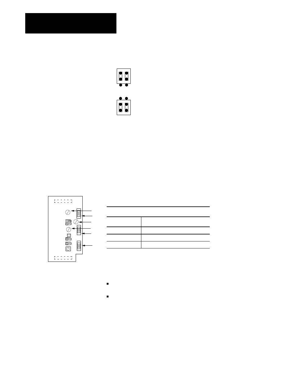
There are three variable resistors (pots) located on the optional feedback
module. Use these pots to adjust the +5V dc output to the non-motor
mounted feedback devices. Figure 4B.21 shows the optional feedback
module pots,corresponding connectors and lists the pots and their
corresponding connectors and pin numbers on the optional feedback module.
Figure 4B.21
Optional Feedback Module Pots and Corresponding Connectors
Optional feedback Module
Pot
Corresponding Connector and Pins
VR1
CN14F, Pins 14, 15, and 16
VR2
CN15F, Pins 14, 15, and 16
VR3
CN16F, Pins 14, 15, and 16
Adjust the pots so that the +5V dc voltage of pins 14, 15, and 16 at the
feedback device end of the feedback cable is within the operating voltage
range of the non-motor mounted feedback device. The pot adjustment
depends on the:
length of the cable running from the optional feedback module to the
non-motor mounted feedback devices
+5V dc operating voltage range of the non-motor mounted feedback
devices
If adjusting the pots does not adjust the +5V dc output so that it falls within
the operating voltage range of the non-motor mounted feedback device, an
external +5V dc power supply is required or the feedback device cable
must be shortened.
4B.3.4
Optional Feedback Module
Variable Resistors (Pots)