Rockwell Automation 8520 9/Series CNC Integration Maintenance Manual Documentation Set User Manual
Page 646
Section 13A
Connecting 8520 Digital Drive Systems
13A-12
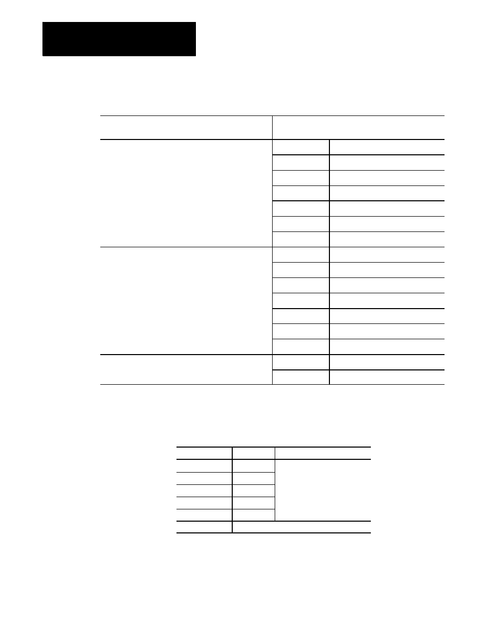
Table 13A.A
Formulas for Determining Transformer Size
If you are using a machine tool application with:
Use this formula to calculate the minimum transformer
KVA
Varying loads on the motor
Number of Axes
Machine Tool Duty
(Machine Tool Duty)
1
KW (Largest Motor) x 0.43 + 0.2
2
KW (Largest Motor) x 0.61 + 0.4
3
KW (Largest Motor) x 0.86 + 0.6
4
KW (Largest Motor) x 1.28 + 0.8
5
KW (Largest Motor) x 1.82 + 1.0
6
KW (Largest Motor) x 2.60 + 1.2
Constant acceleration and deceleration
Number of Axes
Rapid Accel/Decel Duty
(Rapid Accel/Decel Duty)
1
KW (Largest Motor) x 0.60 + 0.2
2
KW (Largest Motor) x 0.85 + 0.4
3
KW (Largest Motor) x 1.20 + 0.6
4
KW (Largest Motor) x 1.80 + 0.8
5
KW (Largest Motor) x 2.50 + 1.0
6
KW (Largest Motor) x 3.50 + 1.2
Motors that perform continuously at or near peak capacity
Number of Axes
Continuous Duty
(Continuous Duty)
All
KW (Total of All Motors) x 1.2 + 1.0
If you are using 8520 digital servo amplifiers, select a transformer from
this list of Allen-Bradley 1389 transformers. Base your selection on the
calculated minimum transformer KVA rating such that the selected
transformer’s KVA rating is equal to or larger than the calculated value:
Catalog Number
Rating (KVA) Primary Voltage and Frequency
1389-T015DA
1.5
240/480V ac, 3
f
60Hz
1389-T035DA
3.5
1389-T050DA
5.0
1389-T100DA
10.0
1389-T125DA
12.5
1391-TA2
NEMA 1 Transformer Enclosure
The dimensions of the Allen-Bradley 1389 transformers are shown in
Figure 13A.8 and Figure 13A.9.