Rockwell Automation 8520 9/Series CNC Integration Maintenance Manual Documentation Set User Manual
Page 495
Section 9A
Operator Interface
9A-28
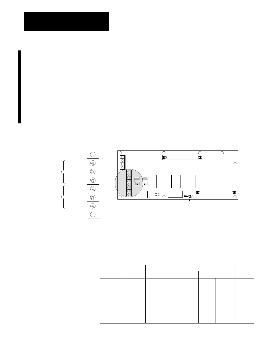
Figure 9A.17 shows the terminal blocks and connectors used to connect
both versions Fiber--Optic push-button MTB panels (incandescent and
LED lamps).
The MTB panel I/O module is interfaced with the system I/O ring using
fiber optic cables that are connected to the optical receiver and transmitter
on the I/O module. Refer to page 7B-1 for additional information on fiber
optic cables and connectors.
The MTB I/O module interfaces the push-button MTB panel with the
control. It provides 44 inputs and 18 outputs to the system I/O ring. These
inputs and outputs provide communication between the push-button MTB
panel and the control.
Figure 9A.17
Push-Button MTB Panel Terminal Block and Connectors
To Main Power
Supply (BT04)
To CNC
Processor Board
(TB1)
PWR
ON
PWR
COM
PWR
OFF
ESTOP
ESTOP
COM
RESET
BT20
+12V DC
GND
OP11
(out)
OP12
(in)
CN51
CN52
I/O ring fault indicator
JPR1
JPR2
Table 9A.J shows the terminal connector used to connect the push-button
MTB panel to the power supply and the CNC processssor.
Table 9A.J
Push-Button MTB Panel Terminal Connector BT-20
Connector On
Connected To
Cable
Push-Button MTB Panel
Component
Connector
Number
PWR ON
Power Supply
ON
PWR COM
BT04
SW
C01
PWR OFF
COM
BT-20
E-STOP
Motherboard/System Processor
E-STOP
E--STOP
COM
BT01
COM
C06
RESET
RESET
9A.4.1
MTB Panel Connectors
and Pin Assignments
(fiber- optic versions)