Brocade TurboIron 24X Series Configuration Guide User Manual
Page 849
Brocade TurboIron 24X Series Configuration Guide
815
53-1003053-01
PIM Sparse
RP2(config-pim-router)#rp-candidate loopback 1
RP2(config-pim-router)#exit
RP2(config)#router msdp
RP2(config-msdp-router)#msdp-peer 10.1.1.1 connect-source loopback 2
RP2(config-msdp-router)#originator-id loopback 2
RP2(config)#ip router-id 10.1.1.2
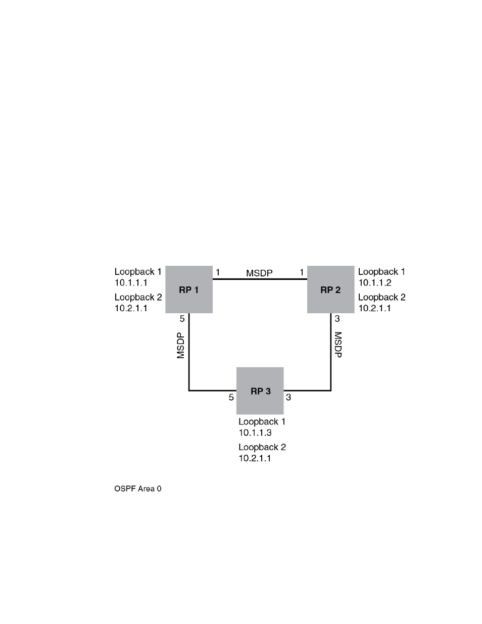
The example shown in Figure 107 is an anycast-enabled network with three RPs connected in a
triangular mesh topology. Loopback 2 in RP 1, RP 2, and RP 3 have the same IP address, which is
the anycast RP address. Loopback 1 in RP1, RP2, and RP3 have different IP addresses and are
configured as MSDP peering IP addresses in a triangular mesh configuration.
OSPF is configured as the IGP for the network and all of the devices are in OSPF area 0. This
example demonstrates only anycast RP configurations. Assuming a PIM-SM network with three
anycast RPs configured, the RP address is configured to be the anycast RP address that was
configured on Loopback interface 2 of RP1, RP2, and RP3. Based on the IGP routes, all routers in
the network are registered to the shortest path anycast RP. This shares the load between all the
RPs, and provides hot backup.
The configuration examples demonstrate the commands required to enable this application.
FIGURE 107
Anycast enabled network in a triangular mesh topology
RP 1 Configuration
The following commands provide the configuration for the RP 1 router in Figure 107.
RP1(config)#router ospf
RP1(config-ospf-router)#area 0
RP1(config-ospf-router)#exit
RP1(config)#interface loopback 1