Configuring device-a, Device-a device-b device-c – Brocade TurboIron 24X Series Configuration Guide User Manual
Page 420
386
Brocade TurboIron 24X Series Configuration Guide
53-1003053-01
Routing between VLANs using virtual routing interfaces (Layer 3 Switches only)
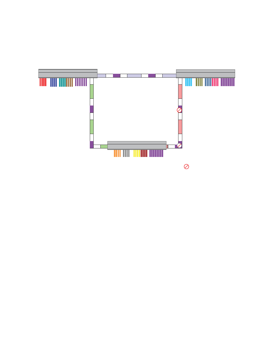
FIGURE 45
Routing between protocol-based VLANs
To configure the Layer 3 VLANs and virtual routing interfaces on the Layer 3 Switch in
,
use the following procedure.
Configuring device-A
Enter the following commands to configure device-A. The following commands enable OSPF or RIP
routing.
TurboIron>en
No password has been assigned yet...
TurboIron#configure terminal
TurboIron(config)#hostname TurboIron-A
TurboIron-A(config)#router ospf
TurboIron-A(config-ospf-router)#area 0.0.0.0 normal
Please save configuration to flash and reboot.
TurboIron-A(config-ospf-router)#
The following commands create the port-based VLAN 2. In the previous example, an external device
defined the router interfaces for VLAN 2. With ISR, routing for VLAN 2 is done locally within each
device. Therefore, there are two ways you can solve this problem. One way is to create a unique IP
subnet and IPX network VLAN, each with its own virtual routing interface and unique IP or IPX
address within VLAN 2 on each device. In this example, this is the configuration used for VLAN 3.
The second way is to split VLAN 2 into two separate port-based VLANs and create a virtual router
interface within each port-based VLAN. Later in this example, this second option is used to create a
port-based VLAN 8 to show that there are multiple ways to accomplish the same task with ISR.
You also need to create the Other-Protocol VLAN within port-based VLAN 2 and 8 to prevent
unwanted protocols from being Layer 2 switched within port-based VLAN 2 or 8. Note that the only
port-based VLAN that requires STP in this example is VLAN 4. You will need to configure the rest of
the network to prevent the need to run STP.
IP
/IPX
Device-A
Device-C
Device-B
Building 1
Building 2
Building 3
Vlan2 Vlan8
Vlan3
Vlan4
Vlan2 Vlan8
Vlan3
Vlan4
Vlan2
Vlan8
Vlan3
Vlan4
= STP Blocked VLAN
V4
V4
V4
V4
V4
V4
V5
V4
IP/IPX
V6
IP/IPX
V6
V6
IP/IPX
V7
IP/IPX
V7
IP/IPX
V5 IP/IPX
Device-A
Device-B
Device-C