Bayer HealthCare Rapidlab 800 User Manual
Page 264
3Ć92
Rapidlab 800 Operator's Manual
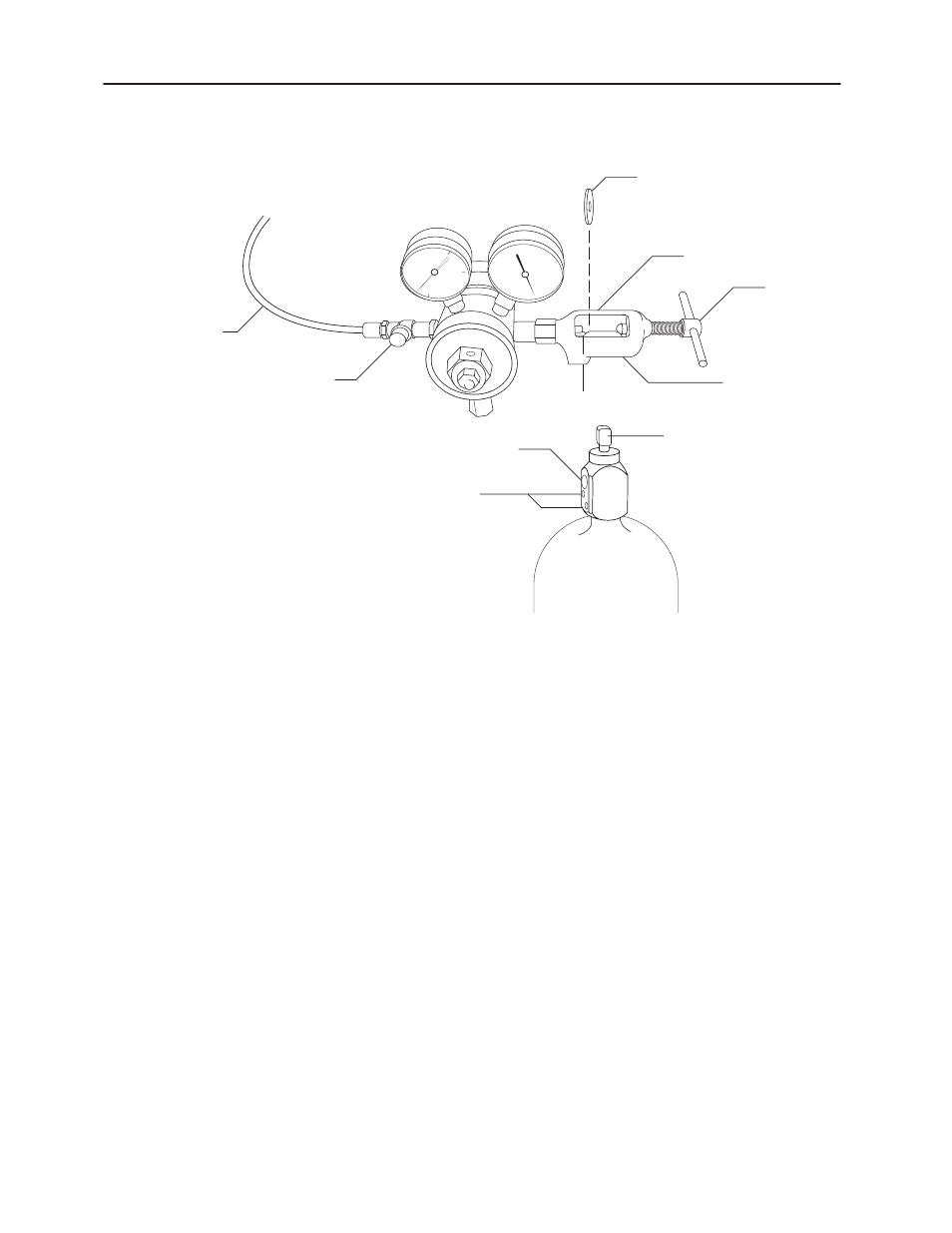
Figure 3Ć62ā.ăGas Tank Valve Assembly and Regulator
Needle Valve
Adjustment Knob
Gas Tank Seal
Regulator Nipple
Yoke
Screw
Gas Line
Yoke
Dowel Pins
Valve Stem
Valve Outlet
Dowel Pin Holes
4.
Install the new gas tank:
a. Check the gas tank label to verify that you are installing the correct gas:
S Bayer Diagnostics Cal Gas contains 5% CO
2
and 12% O
2
S Bayer Diagnostics Slope Gas contains 10% CO
2
and 0% O
2
b. Place the gas tank into its final position and secure the tank.
c. Remove the protective shrink seal from the valve assembly of the gas tank.
d. Verify that the gas tank seal is in good condition and in place on the
regulator, as shown in Figure 3-62.
e. Attach the gas regulator to the gas tank by aligning the regulator nipple
with the valve outlet and ensure that the dowel pins on the regulator-yoke
screw line up properly with the holes in the tank valve, as shown in
Figure 3-62.
f. Tighten the yoke screw firmly.
NOTE:ĄĂ
The typical main tank pressure is 2200 psi. The typical regulator
valve pressure is 3 to 5 psi.
g. Slowly open the gas tank by turning the valve stem counterclockwise with
the wrench until the pressure gauge on the regulator indicates pressure and
then turn it one more turn.