Advanced mct scenario, Configuration considerations, Figure 98 – Brocade BigIron RX Series Configuration Guide User Manual
Page 662: Mct for vrrp or vrrp-e
584
BigIron RX Series Configuration Guide
53-1002484-04
MCT for VRRP or VRRP-E
20
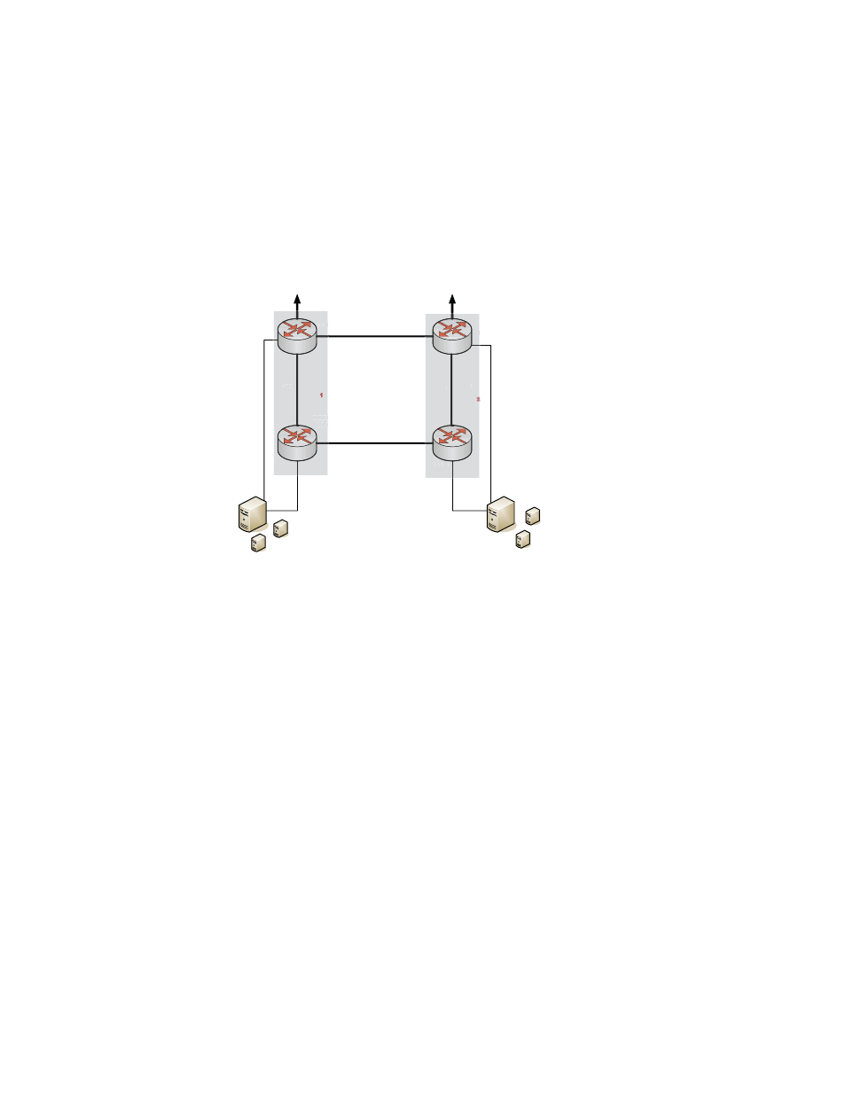
Advanced MCT scenario
shows the advanced MCT scenario. In this scenario, there are two pairs of MCT peer
switches, which are deployed on the two sites that are connected through the two independent
Wide Area Network (WAN) links. Switch A and B form the MCT logical switch 1 and Switch C and D
form the MCT logical switch 2. Switch A acts as the VRRP-E master router and the other MCT
switches (Switch B, Switch C, and Switch D) act as the VRRP-E backup routers. The Layer 2
protocols running on the VRRP-E routers block one of the WAN links to ensure loop-free topology.
FIGURE 98
Advanced MCT scenario
Layer 3 traffic forwarding from an end station to MCT
When Switch A acts as the VRRP or VRRP-E master router and the peer Switch B acts as the VRRP
or VRRP-E backup router as shown in
, the following traffic forwarding behavior is seen:
•
Packets sent to the VRRP-E virtual IP address are Layer 2 switched to Switch A for forwarding.
•
Switch B learns the VRRP-E MAC address from Switch A.
•
Both the data traffic and VRRP-E control traffic travels through the ICL unless the short-path
forwarding behavior is enabled.
When both Switch C and Switch D act as the VRRP or VRRP-E backup routers as shown in
, the following behavior is seen:
•
Packets sent to the VRRP-E virtual IP address are Layer 2 switched to Switch A for forwarding.
•
Switch B that has direct connection to Switch A (master router) learns the VRRP-E MAC address
from the master router. Switch B syncs the learned VRRP-E MAC address to Switch C and
Switch D (backup routers) that do not have direct connection with the master router.
•
Both the data traffic and VRRP-E control traffic travels through the ICL unless the short-path
forwarding behavior is enabled.
Configuration considerations
The following are the configuration considerations for supporting VRRP or VRRP-E for MCT:
VRRP-E Master
10.10.10.254
VRRP-E Backup
To Clients
10.0.0.X
To Clients
10.32.0.X
WAN Link
WAN Link
Virtual server 1
GW: 10.10.10.254
Virtual server 2
GW: 10.10.10.254
Virtual server 4
GW: 10.10.10.254
Virtual server 3
GW: 10.10.10.254
Virtual Servers can move
between ESX1 and ESX 2
VM-Ware ESX 2
VM-Ware ESX 1
VRRP-E Backup
VRRP-E Backup
ICL
ICL
MCT Link
MCT Link
MCT Link
MCT Link
MCT
logical
switch
MCT
logical
switch
VRRP
10.1
VR
ICL
MCT
logical
switch
P
1
RR
E Backup
V
ICL
MCT
logical
switch
E
V
Switch A
Switch B
Switch C
Switch D
1
2
2
2