Configuring the tor-a mct switch, Figure 93 – Brocade BigIron RX Series Configuration Guide User Manual
Page 611
BigIron RX Series Configuration Guide
533
53-1002484-04
Configuring MCT
20
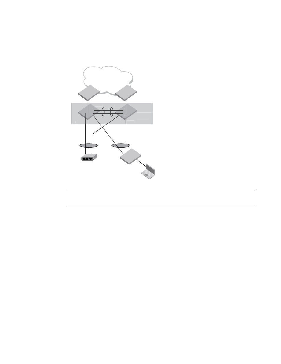
On TOR-A, ports 1/3-1/4 and 1/5 are CCEPs, and port 1/7 is a CEP. On TOR-B, ports 1/3 and 1/4
are CCEPs, and port 1/5 is a CEP. Ports 1/1-1/2 are the ICL ports used for transport of the MCT
control protocol packets or data packets.
FIGURE 93
Single-level MCT
NOTE
Before you begin configuring MCT, save the current configuration files for both the chassis operating
in standalone mode.
Configuring the TOR-A MCT switch
To configure the TOR-A MCT switch as shown in
, perform the following steps.
Creating and deploying the LAGs
You must create and deploy the LAGs on the TOR-A MCT switch. In the example as shown in
, there are three LAGs on the TOR-A MCT switch. One LAG serves as an ICL link and the
other two LAGs are the connections from the MCT switch to the clients (access switches and server
host).
Creating LAG 1
To create LAG 1, perform the following steps.
1. You can either assign a LAG ID explicitly or the system automatically generates a LAG ID. The
LAG ID remains the same across the system reload and hitless upgrade.
The command to configure the LAGs allows explicit configuration of the LAG ID for the static
and dynamic LAGs.
Create a LAG with the LAG ID option by entering the following command.
BigIron RX(config)# lag 1 dynamic
L3 Network
TOR-A
TOR-B
ICL
LAG 2
Client #1
Client #2
1/1-1/3
1/1-1/2
1/3
1/4
1/3
1/5
1/3-1/4
1/7
1/1-1/2
1/1-1/2
1/5
MCT logical
switch
TOR-A
TOR-B
ICL
1/3
1/5
1/3-1/4
1/1-1/2
1
1/1-1/2
2
MCT logical
switch
1/7
LAG 3
LAG 1