Figure 63 – Brocade BigIron RX Series Configuration Guide User Manual
Page 484
406
BigIron RX Series Configuration Guide
53-1002484-04
Metro Ring Protocol (MRP) phase 1
14
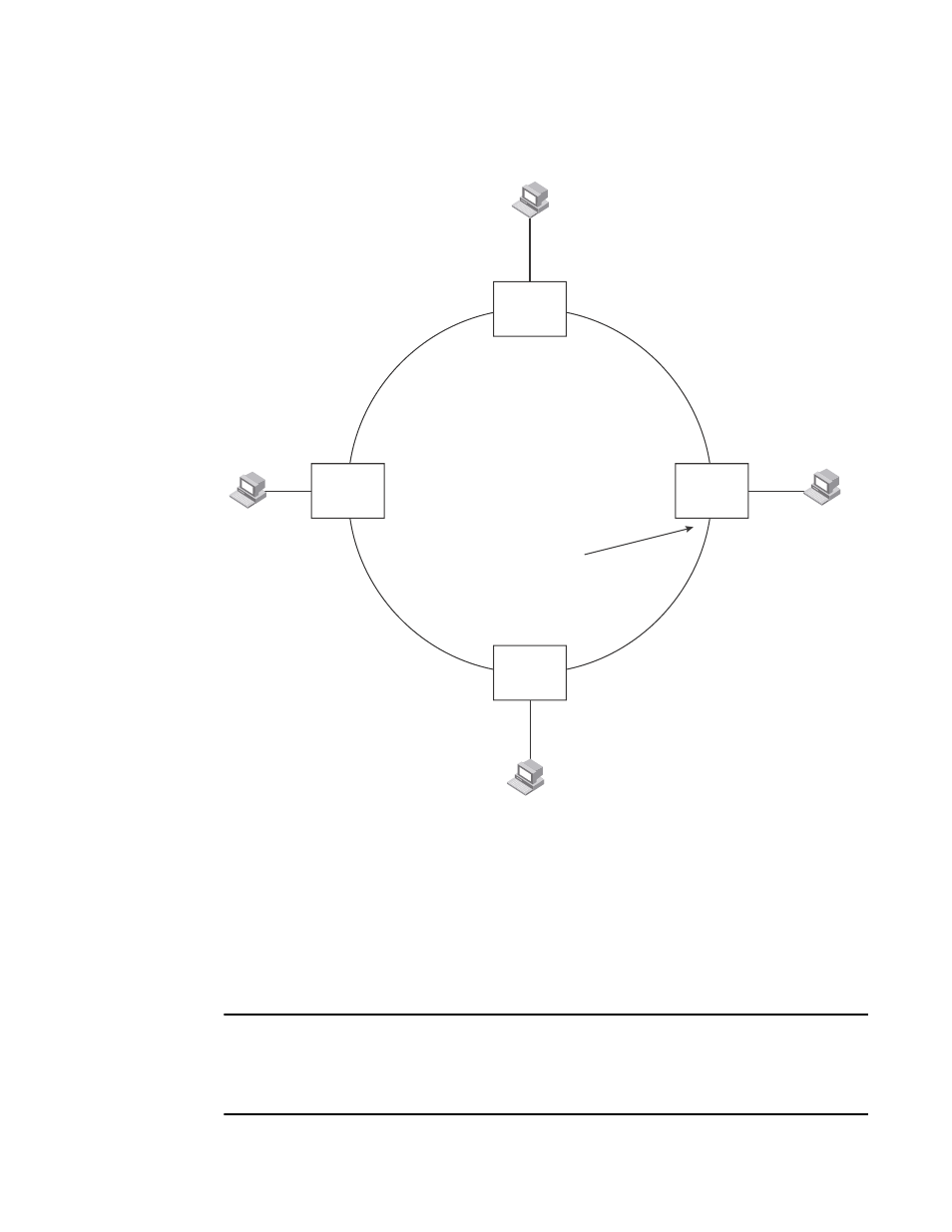
FIGURE 63
Metro ring – normal state
The ring in this example consists of four MRP nodes (Brocade switches). Each node has two
interfaces with the ring. Each node also is connected to a separate customer network. The nodes
forward Layer 2 traffic to and from the customer networks through the ring. The ring interfaces are
all in one port-based VLAN. Each customer interface can be in the same VLAN as the ring or in a
separate VLAN.
One node, is configured as the master node of the MRP ring. One of the two interfaces on the
master node is configured as the primary interface; the other is the secondary interface. The
primary interface originates Ring Health Packets (RHPs), which are used to monitor the health of
the ring. An RHP is forwarded on the ring to the next interface until it reaches the secondary
interface of the master node. The secondary interface blocks the packet to prevent a Layer 2 loop.
NOTE
When you configure MRP, Brocade recommends that you disable one of the ring interfaces before
beginning the ring configuration. Disabling an interface prevents a Layer 2 loop from occurring while
you are configuring MRP on the ring nodes. Once MRP is configured and enabled on all the nodes,
you can re-enable the interface.
F
F
F
Customer A
Member
Node
Switch B
Customer A
Customer A
Customer A
Switch A
Switch C
Switch D
Member
Node
Member
Node
Master
Node
B
F
F
F
F
F
F
F
F
This interface blocks
Layer 2 traffic
to prevent a loop