Arp broadcast resolution – Brocade BigIron RX Series Configuration Guide User Manual
Page 661
BigIron RX Series Configuration Guide
583
53-1002484-04
MCT for VRRP or VRRP-E
20
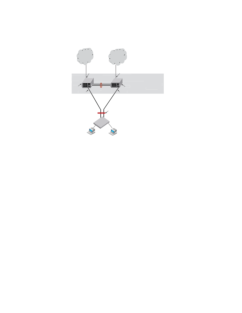
FIGURE 97
Two-node MCT scenario
Layer 3 traffic forwarding from an end station to MCT
When one MCT switch act as the VRRP or VRRP-E master router and the other MCT switch acts as a
VRRP or VRRP-E backup router, as shown in
, the following traffic forwarding behavior is
seen:
•
Packets sent to the VRRP-E virtual IP address are Layer 2 switched to the VRRP-E master router
for forwarding.
•
The VRRP-E backup router learns the VRRP-E MAC address from the VRRP-E master router.
•
Both the data traffic and VRRP-E control traffic travels through the ICL unless the short-path
forwarding behavior is enabled.
Layer 3 traffic forwarding from the CEP to the CCEP
Traffic destined to the CCEP from the client follows the normal IP routing on both the master and
backup routers. By default, the best route must not involve the ICL. Only when the direct link from
the CEP to the CCEP is down, the traffic is re-routed to pass through the ICL.
ARP broadcast resolution
In
, assuming that MCT-unaware switch S1 sends an ARP request (broadcast packet)
through the direct link to Switch B, Switch B sends the request to Switch A for processing through
the ICL. As the MAC learning is disabled on the ICL, the ARP request is not learned automatically
through the ICL. On receiving the ARP request, Switch A sends the response through the direct link
to S1 if the MAC address of S1 is already learned. If the MAC address is not yet learned, the
response packet may be flooded to both the CCEP and ICL ports.
ICL
VRRP-E backup
CCEP
CCEP
MCT unaware switch S1
VRRP-E master
Switch A
Switch B
Clients
Clients
MCT logical
switch
Gateway
Gateway
LAG
CEP
CEP
ICL
VRRP-E backup
CCEP
CCEP
master
Switch A
Switch B
MCT logical
switch
y
y
CEP
CEP
E2
E1