C) automatic calibration – Yokogawa GC8000 Process Gas Chromatograph User Manual
Page 93
<1. Overview>
1-66
IM 11B08A01-01E
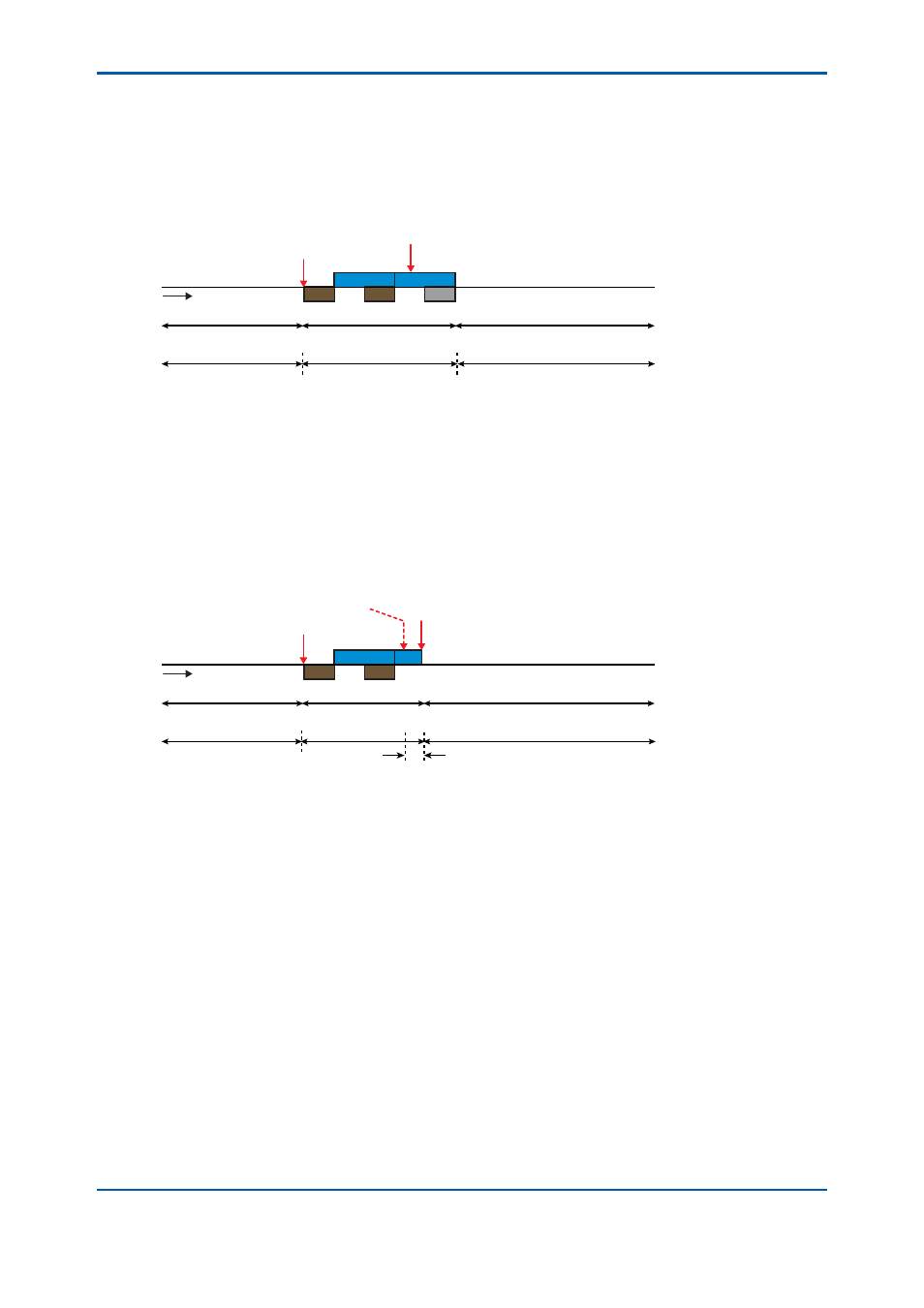
● In the case where a stop command is received during the run mode in the (semiautomatic)
calibration/validation status [4E2]
The operation mode is immediately prepared to be changed to the stop mode in the
calibration (or validation) status.
The operation mode changes to the stop mode in the previous measurement status when
the current measurement is completed.
Run
W7
W7
W8
S7
S7
Time
Stream sequence 1
Calibration 1
Stream sequence 1
Assinning calibration 1
Stop
Stop
[4E2]
Stop command
● In the case where a forced stop command is received during the run mode in the (manual)
calibration/validation status [4F2]
The operation mode is immediately changed to the stop mode in the previous measurement
status.
● In the case where a forced stop command is received when the operation mode is prepared
to be changed from the run mode to the stop mode in the (manual) calibration/validation
status [4F3]
The operation mode is immediately changed to the stop mode in the previous measurement
status.
Stop
Stop
Run
(Waiting for stop)
W7
W7
S7
S7
Time
Stream sequence 1
Calibration 1
Stream sequence 1
Forced stop command
Assinning calibration 1
[4F2] [4F3]
(Stop command)
[4F3]
(c) Automatic calibration
• Stream valves are automatically switched to fl ow the standard sample, then calibration (or
validation) starts automatically at a preset date, time, and interval. The preset calibration (or
validation) patterns of which automatic execution is enabled are automatically executed.
• To select the calibration (or validation) method, touch the “Calibration (validation) method”
button to open the selection window on the GCM operation status screen on the GC-HMI
analyzer operation display (Figure 1.31).
To issue a command to start/stop automatic calibration, touch the “Automatic calibration
start/stop” button to open the confi rmation window on the GCM operation status screen on
the GC-HMI analyzer operation display (Figure 1.32).
On the “Calibration/validation setting” screen on the EtherLCD (Figure 1.33), a set of stream
numbers and the numbers of times of measurement is specifi ed for each of Calibration 1
to 6 and Validation 1 to 6, while the date, time, and interval of automatic start as well as the
validity of automatic calibration are specifi ed.
Users at Level C or higher can cancel the command to change the measurement status
to the specifi ed calibration (or validation) status until the waiting measurement status is
changed to the selected calibration (or validation) number and the measurement of the
currently-measured stream is completed.
2nd Edition : May 11, 2012-00