19 network setup, Redundant setup screen – Yokogawa GC8000 Process Gas Chromatograph User Manual
Page 339
<5. EtherLCD>
5-88
IM 11B08A01-01E
Display Item
Name
Set Lower Limit Upper Limit
Unit
Remarks
Slot #
Slot number
1
5
AI #
A/I input number
1
4
Signal Name A/I signal name
○
Alphanumeric: 8 characters
Filtering const A/I fi ltering constant
○
0.001
1.000
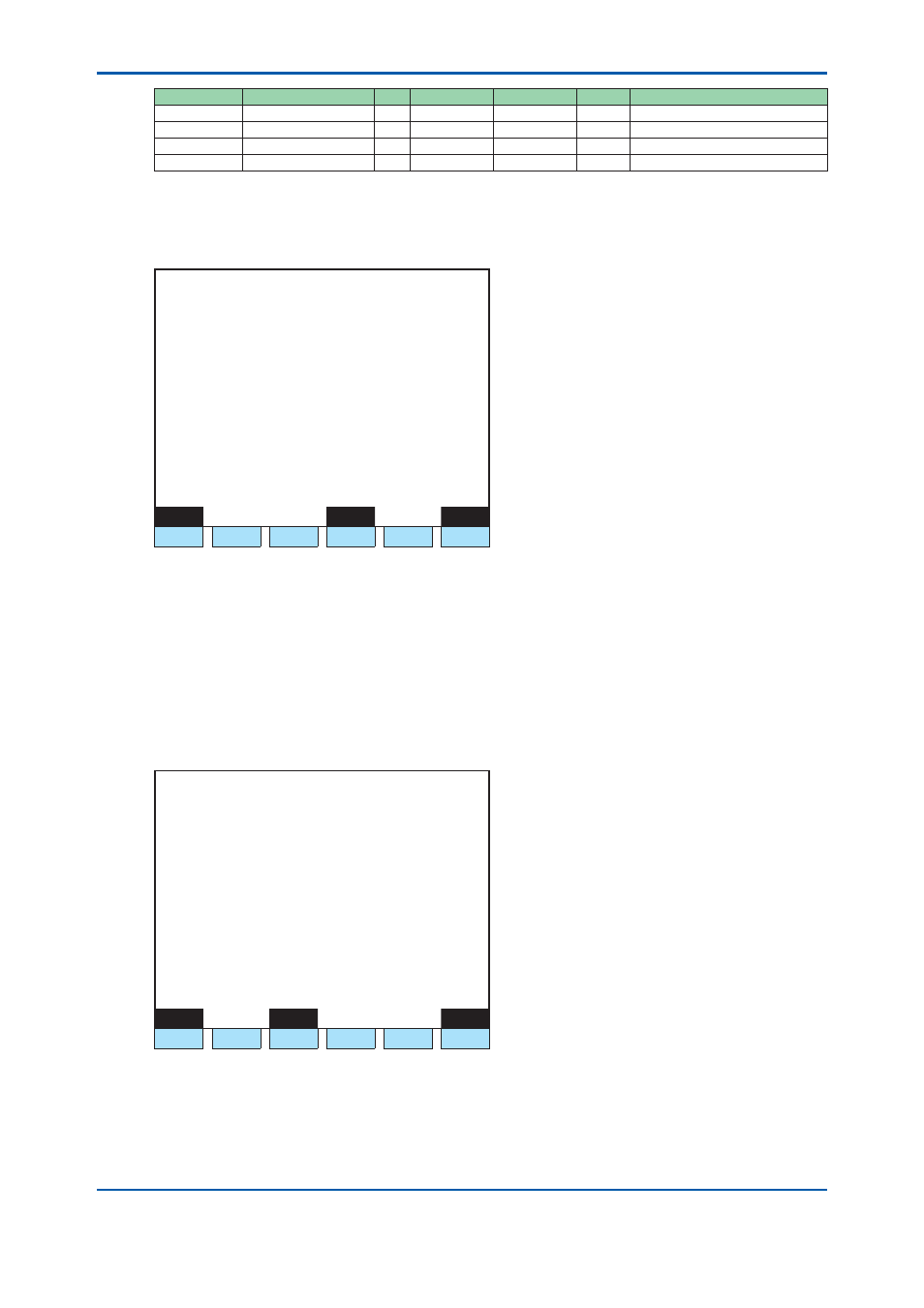
5.4.19 Network
Setup
Set up IP addresses and networks.
1 1 / 1 1 / 2 2
1 5 : 1 5 : 4 5
Network Setup
Main
>
- HY-A IP address 192. 168. 1. 1
- Gateway IP_A 192. 168. 1. 250
- Subnet mask
255. 255. 255. 0
- PCAS confi g Single
- ASGW confi g Single
- DCS confi g Single
- Scaling coef Real
Menu
Redundant
Dial_ip
F1
F2
F3
F4
F5
F6
Figure 5.100
Example of network setup (Main) screen
F1 (Menu):
Displays the Table menu screen.
F4 (Redundant):
Displays the Redundant setup screen.
• F4 (Redundant) is valid only when the Ethernet (ch2) is installed.
Redundant setup screen
Execute the redundant setup.
Press F4 (Redundant).
1 1 / 1 1 / 2 2
1 5 : 1 5 : 4 5
Network Setup
Redundant
>
- Virtual IP address 192. 168. 1. 1
- PHY-B IP address 0. 0. 0. 0
- Gateway IP_B 0. 0. 0. 0
- Diag Interval 500 ms
Menu
Main
Dial_ip
F1
F2
F3
F4
F5
F6
Figure 5.101
Example of network setup (Redundant) screen
F1 (Menu):
Displays the Table menu screen.
F3 (Main):
Displays the Main screen.
2nd Edition : May 11, 2012-00