App.d-3, App.d – Yokogawa GC8000 Process Gas Chromatograph User Manual
Page 448
App.D-3
IM 11B08A01-01E
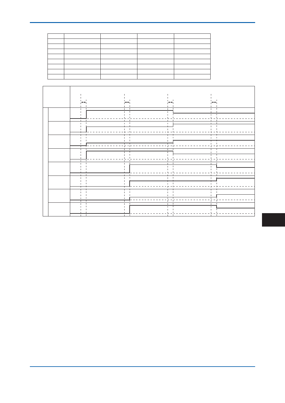
Table 2
Example of Analog Output Settings
Output stream #1 Output peak #1 Output stream #2 Output peak #2
A/O1
1
1
None
None
A/O2
1
2
None
None
A/O3
1
3
None
None
A/O4
1
4
None
None
A/O5
2
1
None
None
A/O6
2
2
None
None
A/O7
2
3
None
None
A/O8
2
4
None
None
F0501.ai
*1
*1
*1
*1
Stream 1
End of Analysis
Stream 2
End of Analysis
Stream 1
End of Analysis
Stream 2
End of Analysis
AO1
AO2
AO3
AO4
AO5
AO6
AO7
AO8
Analog Hold Output
End of Analysis: Time when the final peak detection is completed or peak detection stop time.
*1:
One to two seconds (depending on analysis specifications)
End of Analysis:
End of peak detection time in SYS method
*1:
One to two seconds (depending on analysis specifi cations)
Figure 3 Example of Actions of Analog Output
When Actual Stream is Set for Output Stream Number (with Stream
Identifi cation Signal)
Select Normal output for the AO chromatogram on the A/O setting screen to open the analog
hold output (analysis result output) setting screen (Figure 1). Specify the GCM number, output
stream number, peak number, and the upper and lower limits of the partial range for the peak of
which analysis results are to be output.
Table 3 and Figure 4 show the settings for one GCM with six streams where a stream
identifi cation signal is used.
Table 4 and Figure 5 show the settings for two GCMs with three streams each where a stream
identifi cation signal is used.
2nd Edition : May 11, 2012-00
App.D