15 d/o setup – Yokogawa GC8000 Process Gas Chromatograph User Manual
Page 332
<5. EtherLCD>
5-81
IM 11B08A01-01E
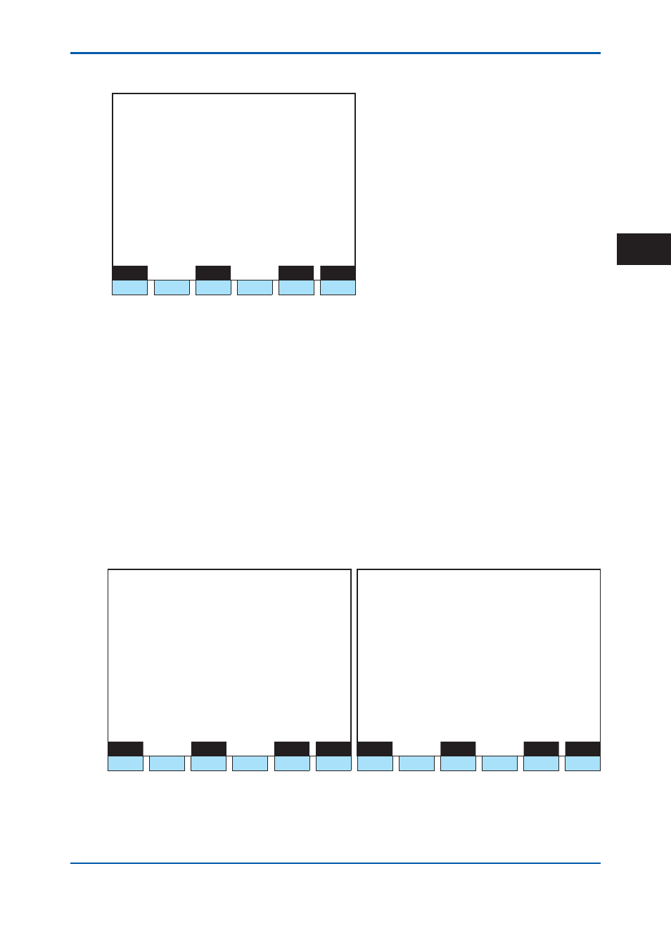
5.4.15 D/O
Setup
1 1 / 1 1 / 2 2
1 5 : 1 5 : 4 5
D/O Setup
Slot # 1 DO # 1
>
- Process assign Operation mode
- GCM number 1
- Operation mode Stop
Menu
Status
Slot#
DO#
F1
F2
F3
F4
F5
F6
Figure 5.89
Example of D/O setup screen
F1 (Menu):
Displays the Table menu screen.
F3 (Status):
Displays the D/O status screen.
F5 (Slot #):
Specifi es a slot number.
F6 (DO #):
Specifi es a D/O number.
• A D/O contact number displays the relative number of each SLOT.
• When F5 (Slot #) is pressed, Slot #: is displayed at the bottom line. When a slot number
is entered and SET/ENT key is pressed, the set value of the specifi ed slot number is
displayed.
• When setting the slot number, if a card other than D/O or DI/O is installed in the relevant
slot, any entry is not accepted.
• When F6 (DO#) is pressed, DO #: is displayed at the bottom line (the default is 1). When
D/O number is entered and SET/ENT key is pressed, the set value of the specifi ed D/O
number is displayed.
• When any D/O number is used for stream identifi cation on the GCM setup screen , the
Process assign displays ****** and not selectable.
1 1 / 1 1 / 2 2
1 5 : 1 5 : 4 5
D/O Setup
(1/2)
1 1 / 1 1 / 2 2
1 5 : 1 5 : 4 5
D/O Setup
(2/2)
Slot #
1 DO # 1
Slot #
1 DO # 1
>
- Process assign Stream sequence
>
- Stream sequence 7 AAAAAAA
- GCM number 1
- Stream sequence 8 AAAAAAA
- Stream sequence 1 AAAAAAA
- Stream sequence 2 AAAAAAA
- Stream sequence 3 AAAAAAA
- Stream sequence 4 AAAAAAA
- Stream sequence 5 AAAAAAA
- Stream sequence 6 AAAAAAA
Menu
Status
Slot#
DO#
Menu
Status
Slot#
DO#
F1
F2
F3
F4
F5
F6
F1
F2
F3
F4
F5
F6
Figure 5.90
Example of D/O setup screen (setting the Process assign to stream sequence)
When the stream sequence is set in the Process assign, items to set up specifi ed output of each
stream sequence are added, and all two pages are displayed.
2nd Edition : May 11, 2012-00
5