Yokogawa GC8000 Process Gas Chromatograph User Manual
Page 49
<1. Overview>
1-22
IM 11B08A01-01E
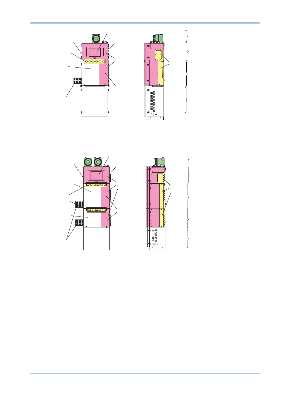
Protection system *1
Control unit
Oven unit 1
Analyzer base
sampling unit *2
/Up to 6 streams
+ standard gas (liquid)
Flow
control
section
Warning plate
GC-HMI (touch panel) *3
Electronics
section
EPC box *3
LSV (liquid
sample valve) *3
Pressure
control
section *3
Large
isothermal
oven section
Data plate
*1 The
specifi cation decides the number of the fl ameproof enclosure of the protection system.
*2
A stanchion or GCSMP can be mounted on the self-standing type.
External sampling systems can be connected as needed.
*3
Depending on the specifi cations.
Figure 1.3
Structure and components of Type 1
Protection system *1
Control unit
Oven unit 1
Oven unit 2
Analyzer base
sampling unit *2
/Up to 6 streams
+ standard gas (liquid)
Flow
control
section
Warning plate
GC-HMI (touch panel) *3
Electronics
section
EPC box *3
LSV (liquid
sample valve) *3
Pressure
control
section *3
Large
isothermal
oven section
Isothermal
oven
section
Data plate
*1 The
specifi cation decides the number of the fl ameproof enclosure of the protection system.
*2
A GCSMP can be mounted on the self-standing type.
External sampling systems can be connected as needed.
*3
Depending on the specifi cations.
Figure 1.4
Structure and components of Type 2
2nd Edition : May 11, 2012-00