Gate action setting screen – Yokogawa GC8000 Process Gas Chromatograph User Manual
Page 308
<5. EtherLCD>
5-57
IM 11B08A01-01E
F1(Main):
Displays SYS Method Setup screen (Main).
F2(Gate):
Displays Action Set (gate) in the action set screen.
F3(Valve):
Displays ON/OFF time screen in a valve (1st, 2nd & 3rd of the maximum No. 1
to No. 18).
F4(Atm):
Displays ON/OFF time screen of ATM Valve (1st, 2nd & 3rd).
F5(DO):
Displays D/O Setup screen in the action set screen.
F6(Strm#): Specifi es a stream number.
• Stream number is assigned with F6 (Stm #). Only the stream number being used by the
relevant GCM number can be set. The smallest stream number is displayed in the initial
display.
• Up to 512 sequences can be displayed.
• SYS sequence with SYS usage set as “Not executed” is also displayed.
• Gate ON/OFF time for the peak not executed is not displayed.
• Base/signal/noise level and A/I signals 1 to 4 of the action time are displayed.
• When D/O is not installed, F5 (DO) is not displayed.
• When any peak is not assigned, selecting F2 (gate) displays the message “No assignment
peak of request tream.”
Display Item
Name
Set Lower Limit Upper Limit
Unit
Remarks
GCM #
GCM number
1
6
SYS #
SYS number
1
6
Method #
Method number
1
6
Stream #
Stream number
1
31
Time
Action
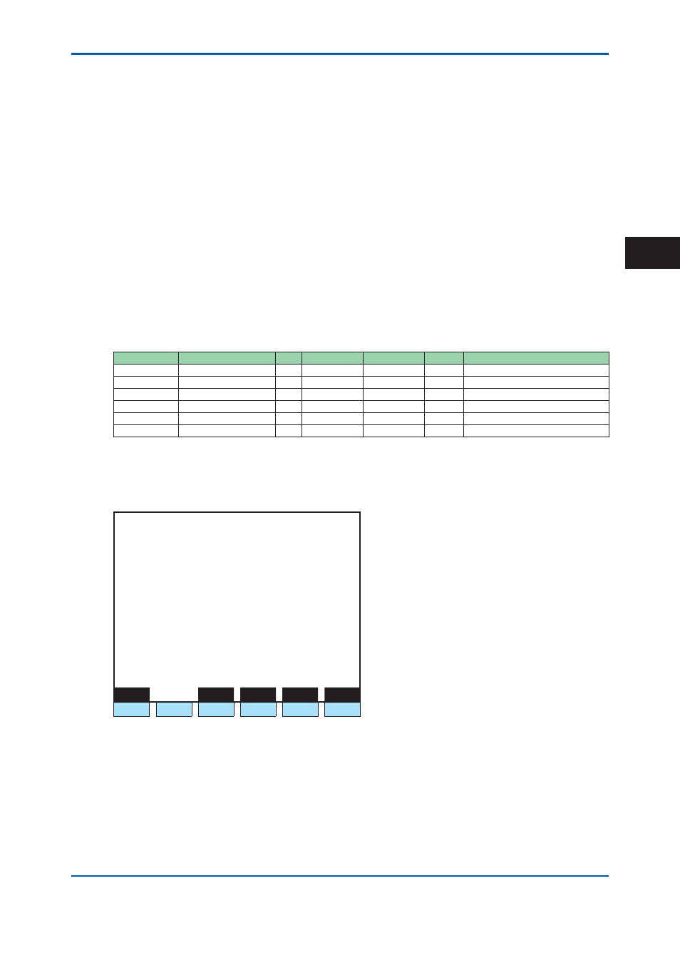
Gate Action Setting Screen
Press F2 (Gate).
1 1 / 1 1 / 2 2
1 5 : 1 5 : 4 5
Gate Action Setting
GCM #1 / SYS #1 / Method #1 / Stream #1
Peak number 1
>
- Gate ON time
1.0 s
- Gate OFF time
5.0 s
Main
Valve
AtmV
DO
Peak#
F1
F2
F3
F4
F5
F6
Figure 5.71
Example of the gate action setting screen
F1(Seq):
Displays SYS Sequential Display screen.
F3(Valve):
Displays Valve screen of the action set screen.
F4(Atm):
Displays ON/OFF time screen of ATM Valve (1st, 2nd & 3rd).
F5(DO):
Displays D/O Setup screen in the action set screen.
F6(Peak#): Specifi es a peak number (relative peak number).
• Sets possible for User Level C and above.
2nd Edition : May 11, 2012-00
5