12 alarm setup – Yokogawa GC8000 Process Gas Chromatograph User Manual
Page 329
<5. EtherLCD>
5-78
IM 11B08A01-01E
5.4.12 Alarm
Setup
1 1 / 1 1 / 2 2
1 5 : 1 5 : 4 5
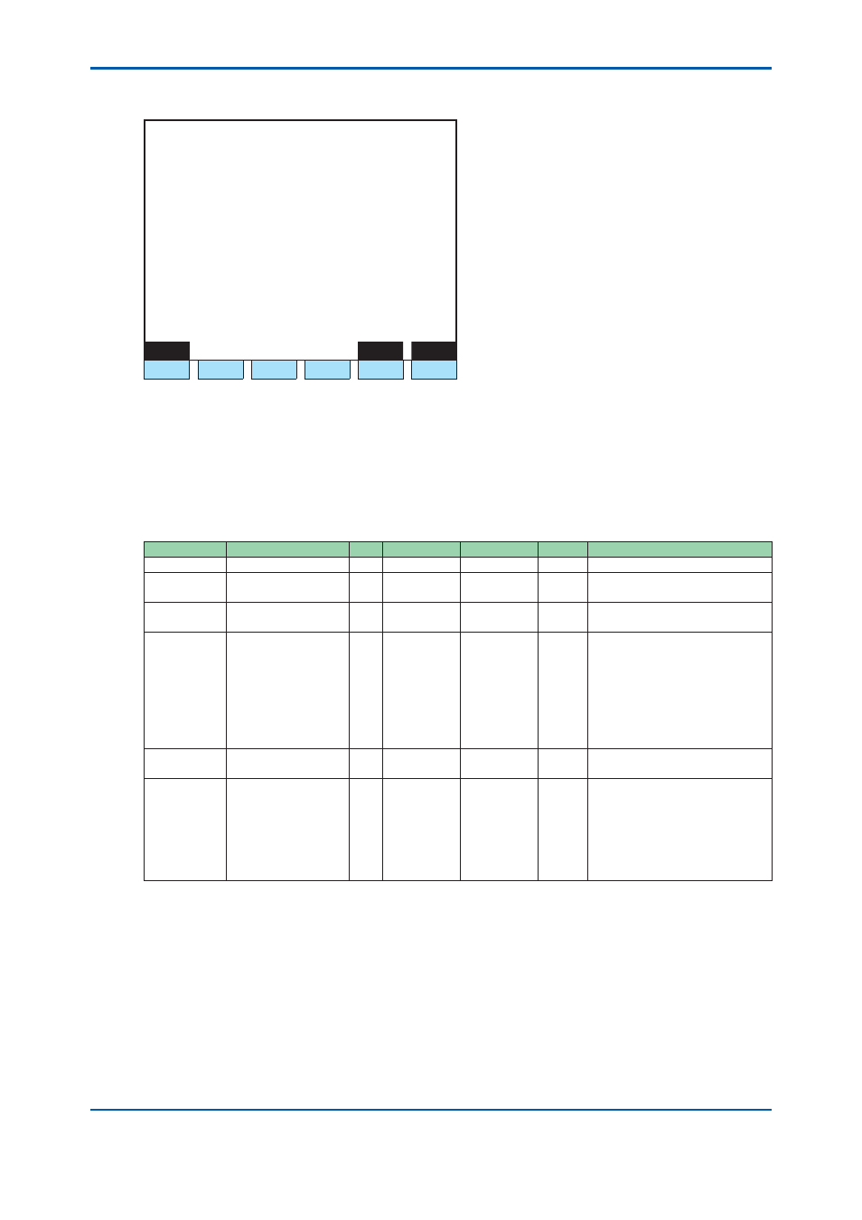
Alarm Setup
GCM # 1 Set # 1
>
- Stream number 2
Peak number 1
- Check item Conc
- Maximum 0.000
- Minimum 0.000
Menu
GCM#
Set#
F1
F2
F3
F4
F5
F6
Figure 5.86
Example of alarm setup screen
F1 (Menu):
Displays the Table Menu screen.
F5 (GCM #): Specifi es a GCM number.
F6 (Set #):
Sets an alarm number.
• When a stream and a peak number in database are both zero, they are assessed as no
settings and all data is displayed with * (asterisk).
Display Item
Name
Set Lower Limit Upper Limit
Unit
Remarks
GCM #
Set #
Relevant set number (1 to 32),
32 per GCM (Total 192)
Stream
number
○
(0), 1
31
99 can also be entered.
Peak number
(0), 1
999
When a stream number is 99,
all streams belonging to GCM is
applicable and a relative peak
number is assigned to the peak
number.
Assign 0 to the stream number
and the peak number to enable
setting invalid data.
Check items
○
Alarm check items, Density, R.
Time, Vari coeff, Tailing coeff
Upper Limit,
Lower Limit
○
Density: −999.999 to 9999.999
(Process assign is A/I signal),
0.000 to 9999.999 (Process
assign is other than A/I signal)
R. Time:0.000 to 21600.0 sec
Vari coeff: 0.000 to 1.999
Tailing coeff: 0.000 to100.000
2nd Edition : May 11, 2012-00