D/o action setting screen – Yokogawa GC8000 Process Gas Chromatograph User Manual
Page 311
<5. EtherLCD>
5-60
IM 11B08A01-01E
Display Item
Name
Set Lower Limit Upper Limit
Unit
Remarks
GCM #
GCM number
1
6
SYS #
SYS number
1
6
Method #
Method number
1
6
ATM valve
ATM valve number
0
3 − 2
0: None
1 to 3 Oven
1 to 2 ATM valve
1st to 3rd ON
time
○
−Warming
up time
Analysis
cycle − 2
seconds ATM valve time setup
Some entry data are invalid.
1st to 3rd
OFF time
○
seconds
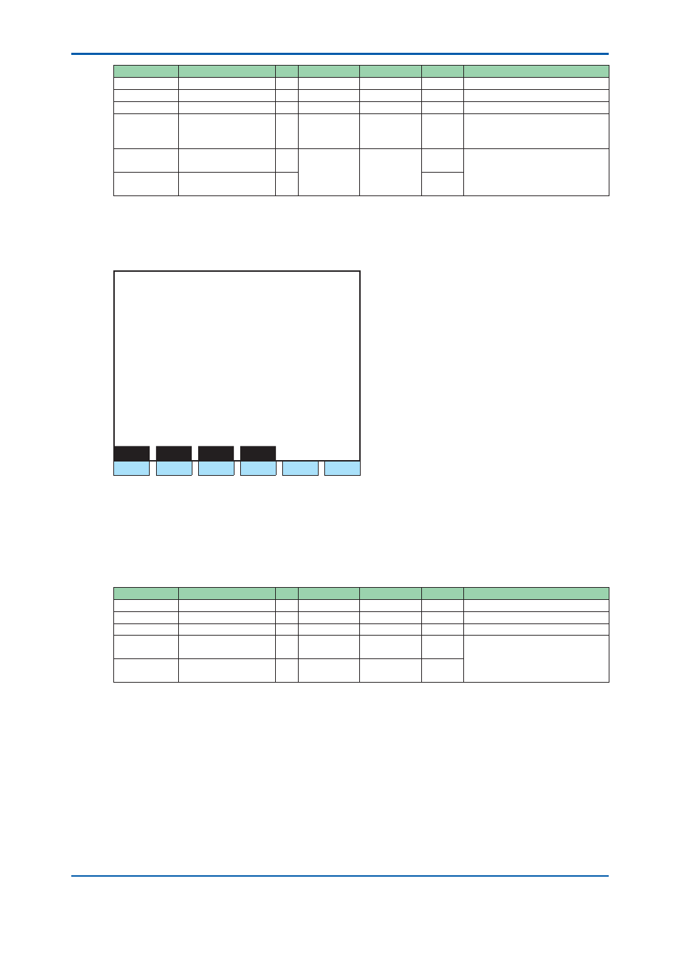
D/O Action Setting Screen
Press F5 (DO).
1 1 / 1 1 / 2 2
1 5 : 1 5 : 4 5
D/O Action Setting
GCM #1 / SYS #1 / Method #1
> - 1st DO ON time * * * * * * * s
- 1st DO OFF time * * * * * * * s
- 2nd DO ON time
* * * * * * * s
- 2nd DO OFF time * * * * * * * s
- 3rd DO ON time
* * * * * * * s
- 2nd DO OFF time * * * * * * * s
Seq
Gate
Valve
AtmV
F1
F2
F3
F4
F5
F6
Figure 5.74
Example of the D/O action setting screen
F1(Seq):
Displays SYS Sequential Display screen.
F2(Gate):
Displays Gate of the action set screen.
F3(Valve):
Displays ON/OFF time screen of a valve (1st, 2nd & 3rd of the maximum No. 1
to No. 18).
F4(Atm):
Displays ON/OFF time screen of ATM valve (1st, 2nd & 3rd).
Display Item
Name
Set Lower Limit Upper Limit
Unit
Remarks
GCM #
GCM number
1
6
SYS #
SYS number
1
6
Method #
Method number
1
6
1st to 3rd ON
Time
○
0
Analysis
cycle − 2
seconds D/O time setup
Some entry data are invalid.
* When ON time is invalid, the
minimum OFF time is 0.
1st to 3rd
OFF Time
○
ON time
Analysis
cycle − 2
seconds
2nd Edition : May 11, 2012-00