Contact output (ac) (code: 8) (g) (l) – Yokogawa GC8000 Process Gas Chromatograph User Manual
Page 148
<2. Installation, Piping, and Wiring>
2-31
IM 11B08A01-01E
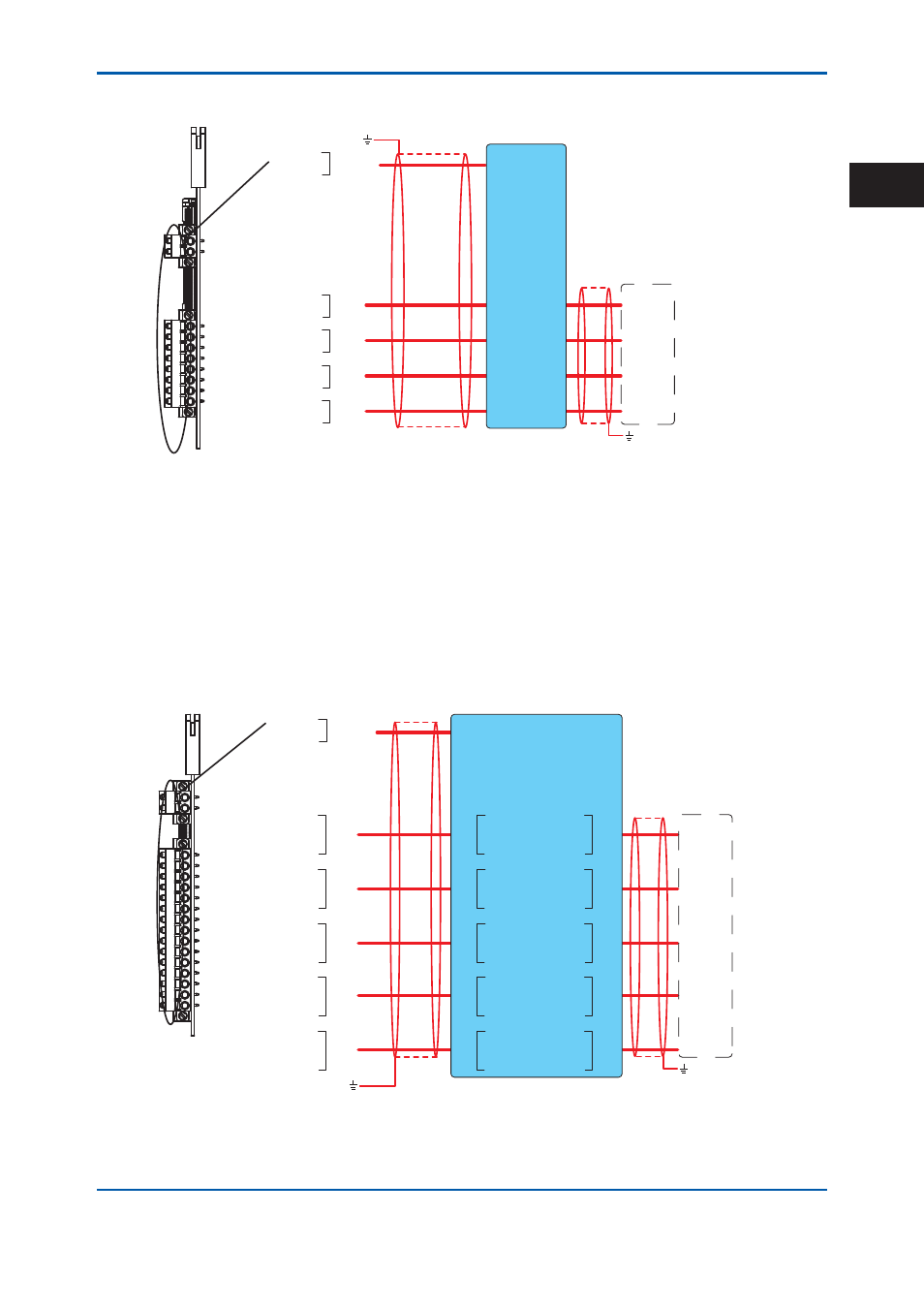
Analog input (voltage) (Code: 3) and analog input (current) (Code: 4) (E) (L)
1
2
11
12
13
14
15
16
17
18
1
2
11
12
13
14
15
16
17
18
AI1
AI2
AI3
AI4
+
-
+
-
+
-
+
-
(E)
(E)
(E)
(E)
V1 +
V1 -
24V DC
(L)
*1 *2
*1
*1
V+
V-
11 1+
12 1-
13 2+
14 2-
15 3+
16 3-
17 4+
18 4-
1+ 21
1- 22
2+ 23
2- 24
3+ 25
3- 26
4+ 27
4- 28
*3
Signal interrupter K9806AE
*1: This is not used for FM-Y.
*2: The ground wire is connected to the earth bar.
*3: The ground wire is connected to the earth terminal on site.
Figure 2.29
Wiring for an analog input card
The analog input card is labeled “AI”.
The external I/O cutoff output (power cutoff signal) (L) is also wired.
The shield is grounded at the earth bar in Figure 2.22. Remove the cover on the upper right of the
electronics section and perform wiring.
Contact output (AC) (Code: 8) (G) (L)
1
2
11
12
13
14
15
16
17
18
19
20
21
22
23
24
25
1
2
11
12
13
14
15
16
17
18
19
20
21
22
23
24
25
V1 +
V1 -
24V DC
(L)
(G)
(G)
(G)
(G)
(G)
*1
*2
*1
*1
DO1
DO2
DO3
DO4
DO5
V +
V -
*3
DO1
DO2
DO3
DO4
DO5
DO1
DO2
DO3
DO4
DO5
K9806AN
NO 31
COM 32
NO 33
COM 34
NO 35
COM 36
NO 37
COM 38
NO 41
COM 42
11 NO
12 COM
13 NO
14 COM
15 NO
16 COM
17 NO
18 COM
21 NO
22 COM
NO
COM
NO
COM
NO
COM
NO
COM
NO
COM
*1: This is not used for FM-Y.
*2: The ground wire is connected to the earth bar.
*3: The ground wire is connected to the earth terminal on site.
Signal interrupter
Figure 2.30
Wiring for a contact output card
2nd Edition : May 11, 2012-00
2