16 d/i setup – Yokogawa GC8000 Process Gas Chromatograph User Manual
Page 335
<5. EtherLCD>
5-84
IM 11B08A01-01E
Display Item
Name
Set Lower Limit Upper Limit
Unit
Remarks
Slot #
1
5
Limited
DO #
1
5
Limited
Process
assignment
○
No process, Stream sequence,
Stream, Operation mode, Alarm,
Timing, Cal/Val, Str valve select
GCM number
○
1, (0)
6
Setting possible only when 1(0)
to 6, process assign entails
stream sequence, cal (val),
operation mode and alarm. In
the case of alarm, GCM number
0 is applicable to all GCEX
alarm. GCM number range is 1
to 6 when other than alarm.
Stream
sequence 1
to 8
○
No output, Output
Initial value for stream sequence
1 only has Output. Others have
No output.
Stream
number
○
1
31
Operation
mode
○
Run, Run (including warming up
time), Stop, Pause
Alarm
level 1, 2,
Composition
alarm
○
No output, Output
SYS Number
○
1
6
Limited
SYS method
○
1
6
Limited
1st to 3rd
times
○
No output, Output
Cal 1 to 6
○
No output, Output
Val 1 to 6
○
No output, Output
Stream valve
number
○
1
31
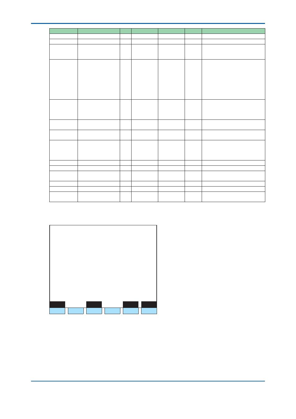
5.4.16 D/I
Setup
1 1 / 1 1 / 2 2
1 5 : 1 5 : 4 5
D/I Setup
Slot #
1 DI # 1
>
- Signal name
- Process assign Range Select
- Stream number 1 (GCM 1)
Peak number 1
- Range number 1
Menu
Status
Slot#
DI#
F1
F2
F3
F4
F5
F6
Figure 5.97
Example of D/I setup screen
F1 (Menu):
Displays the Table menu screen.
F3 (Status):
Displays the D/I status screen.
F5 (Slot#):
Sets a slot number.
F6 (DI#):
Sets a D/I number.
2nd Edition : May 11, 2012-00