App.d-5, App.d – Yokogawa GC8000 Process Gas Chromatograph User Manual
Page 450
App.D-5
IM 11B08A01-01E
1 1 / 1 1 / 2 2
1 5 : 1 5 : 4 5
GCM Setup
(2/2)
1 1 / 1 1 / 2 2
1 5 : 1 5 : 4 5
GCM Setup
(2/2)
GCM # 1
GCM # 1
>
- ATM valve number 1-1
>
- ATM valve number 1-2
Strm identifying Up to 7 streams
Strm identifying Up to 7 streams
- 1st num StrIdentify DO
Slot #4 -#1
- 1st num StrIdentify DO
Slot #5 -#1
- 1st num StrValve 1
- 1st num StrValve 4
- Stream valve num 3
- Stream valve num 3
- Distillation
None
- Distillation
None
Menu
GCM#
Menu
GCM#
F1
F2
F3
F4
F5
F6
F1
F2
F3
F4
F5
F6
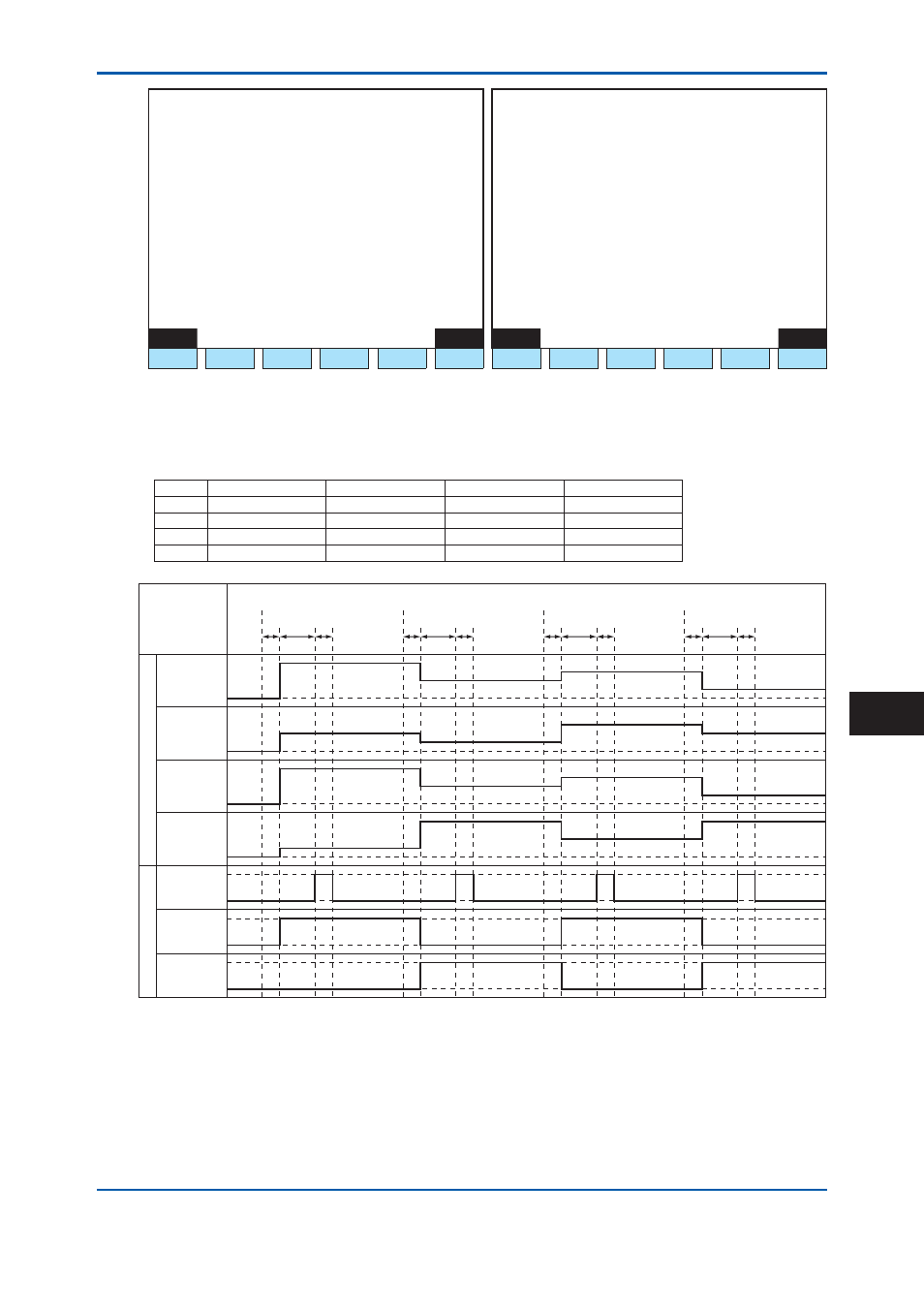
Figure 5 Stream Identifi cation Signal Output: Exist (GCM Setting Screen on GC-HMI EtherLCD)
Table 5 shows an example of analog output settings.
Figure 6 illustrates respective actions.
Table 5
Example of Analog Output Settings
Output stream #1 Output peak #1 Output stream #2 Output peak #2
A/O1
1
1
2
1
A/O2
1
2
2
2
A/O3
1
3
2
3
A/O4
1
4
2
4
F0502.ai
*1
2s
4s
2s
4s
2s
4s
2s
4s
*1
*1
*1
Stream 1
End of Analysis
Stream 2
End of Analysis
Stream 1
End of Analysis
Stream 2
End of Analysis
AO1
AO2
AO3
AO4
DO3
(Stream
identification
flag)
DO4
(Stream
identification
signal)
DO5
(Stream
identification
signal)
Analog Hold Output
Contact Output
End of Analysis: Time when the final peak detection is completed or peak detection stop time.
*1:
One to two seconds (depending on analysis specifications)
End of Analysis:
End of peak detection time in SYS method
*1:
One to two seconds (depending on analysis specifi cations)
Figure 6
Example of Actions of Analog Output
2nd Edition : May 11, 2012-00
App.D