Yokogawa GC8000 Process Gas Chromatograph User Manual
Page 52
<1. Overview>
1-25
IM 11B08A01-01E
Cover
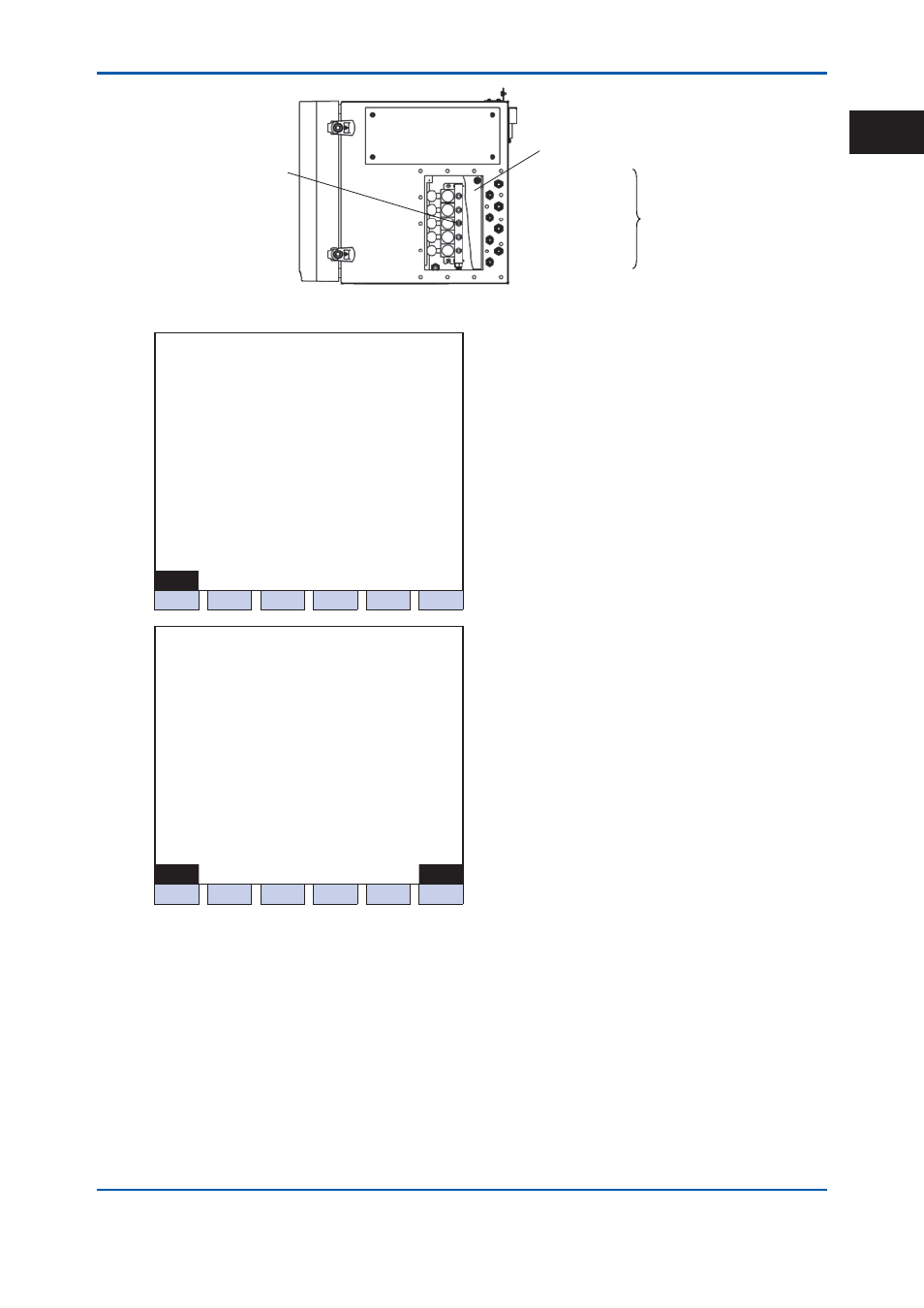
Air output for
stream swiching valve
(connection: 6 mm or
1/4 inch tube,
pressure: 350kPa)
Air OUT 2
Air OUT 1
Air OUT 4
Air OUT 3
Air OUT 6
Air OUT 5
Air OUT 8
Air OUT 7
Manifold regulators
Figure 1.6
Pressure control section of the control unit
11/03/22
15:15:45
Operating Parameters (7/8)
> - SV air press
350
- Elec Purge press
350
Menu
Menu
Menu
Menu Oven#
Gas#
F1
F2
F3
F4
F5
F6
11/03/22
15:15:45
Operating Parameters (8/8)
Oven #1
- Oven air Press
200
- TPM Vortex press
****************
> - FPD Vortex press
Menu
Menu
Menu
Menu Oven# Oven#
F1
F2
F3
F4
F5
F6
Figure 1.7
Example of the operation condition confi guration screen of the GC-HMI (touch panel)
EtherLCD
(b) Pressure and fl ow control section of the oven
In the case of the large isothermal oven or isothermal oven, the pressure and fl ow rate control
section is equipped on the front and right side of the oven unit. In the case of the programmed-
temperature oven, this section is equipped only on the right side of the oven unit.
The pressure regulators with a pressure gauge for utility gases 1 to 4 are equipped in sequence
from right to left on the front of the oven unit, followed by the pressure gauges for carrier gases 1
to 2.
The connections for the following purposes are on the right side of the oven unit.
2nd Edition : May 11, 2012-00
1