Caution, Gland assembly – Yokogawa GC8000 Process Gas Chromatograph User Manual
Page 389
<6. Maintenance>
6-36
IM 11B08A01-01E
CAUTION
The isothermal oven is extremely hot after turning off the power immediately. Keep the purging
air supplied for more than an hour after turning off the power. Keep hands away from the oven
components.
(6) Turn off the supply of the purging air and carrier gas. For a detection system with an FID,
turn off the supply of hydrogen (or nitrogen) gas and combustion air as well.
(7) Open the control unit door using a key included in the accessory kit.
(8) Remove the couplings connected to the rotary valve. When removing the couplings, label
them for ease of identifying the connections later. The rotary valve is either a single-sleeve
or double-sleeve type, depending on the specifi cations. Each type comprises four to six
pipes extending from the sleeve.
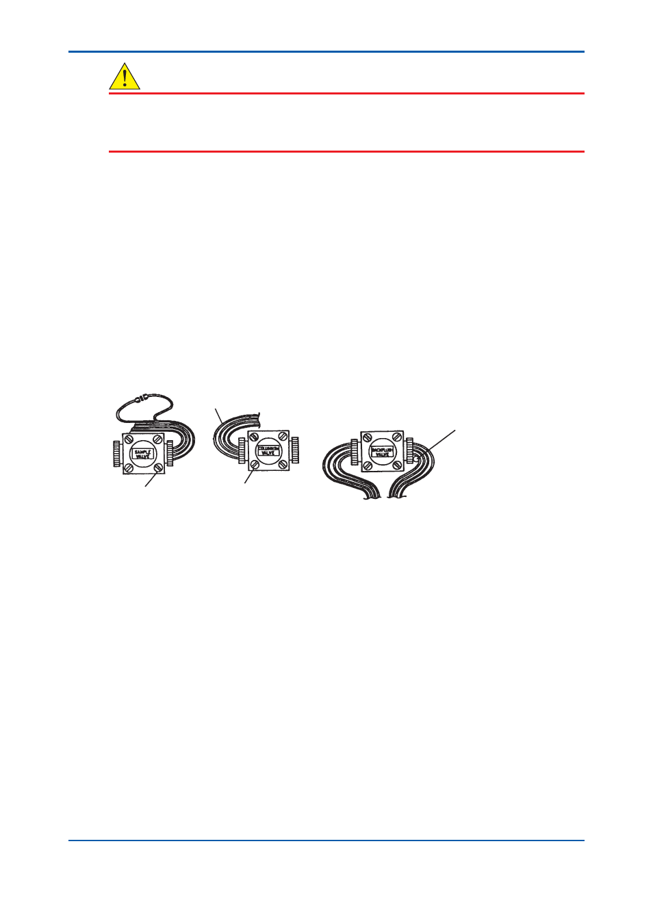
(9) Remove the two screws which are not painted with red enamel to disassemble the rotary
valve. Do not touch the two screws which are painted red.
(10) Install a new rotary valve. When installing it, it is necessary to bend pipes as shown in Figure
6.31. When bending a pipe, use another pipe that is approximately 10mm in diameter to
support it and avoid excessive force applied on the root of the pipe. The cap nuts at the tip of
the pipes are inscribed with numbers. Engage these cap nuts according to the pre-labeled
numbers or per column system diagram in the operation data.
(11)
Perform a leak test on the piping.
F0231.ai
ø10 mm pipe
Rotary valve
mounting screws
ø1.6 mm tubes
Do not loosen the screws
with red enamel paint.
Sample valve
Column switching valve
Backflush valve
Figure 6.31
Replacing rotary valves
Gland assembly
See Figure 6.32.
(1) Stop the operation. (See “3.3.4 Stopping operation” for this procedure).
(2) Turn off supply of the sample.
(3) If the sample is liquid, purge the sample line with the purge gas (nitrogen gas or instrument
air).
• When the stream switching valve is a pneumatic valve, change the analyzer status to
Manual and turn on the stream switching valve on the sample line to let the purge gas fl ow
in.
• When the stream switching valve is a stop valve, close all the stop valves and open the stop
valve on the sample line to let the purge gas fl ow in.
(4) Close all the stream switching valves.
2nd Edition : May 11, 2012-00