App.d-18, Calibration/validation – Yokogawa GC8000 Process Gas Chromatograph User Manual
Page 463
App.D-18
IM 11B08A01-01E
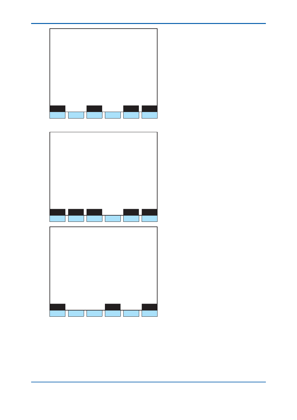
1 1 / 1 1 / 2 2
1 5 : 1 5 : 4 5
D/I Setup
Slot #
1 DI # 1
>
- Signal name S1P1-R1
- Process assign Range Select
- Stream number 1 (GCM 1)
- Peak number 1
- Range number 1
Menu
Status
Slot#
DI#
F1
F2
F3
F4
F5
F6
Figure 24 Process Specifi cation: Range Switching (D/I Setting Screen on GC-HMI EtherLCD)
1 1 / 1 1 / 2 2
1 5 : 1 5 : 4 5
Peak Setup-Specifi c
(2/5)
Stream #1 Peak #1 External 3rd
- Detector number 1-1
>
- Measuring unit 1
- Measuring range 100.000
- Gate cut method Slope gate
- Integ method
Skimming
- Peak polarity Positive
- Detected slope 0.0010 mV/s
Menu
Copy1
Copy2
Strm#
Peak#
F1
F2
F3
F4
F5
F6
1 1 / 1 1 / 2 2
1 5 : 1 5 : 4 5
Multirange Setup
Range # 1
>
- Process (Type) Peak
- Process (Detail)
External 3rd
- Measuring unit 1
- Measuring range 50.000
- Ref peak number #40 #001
Menu
Get
Range#
F1
F2
F3
F4
F5
F6
Figure 25 Individual Peak Setting Screen and Multi-Range Setting Screen on GC-HMI EtherLCD
Calibration/Validation
The Calibration/Validation function of D/I is a function to give a command to change the
measurement status to the status of a specifi ed calibration or validation number using contact
input as a trigger.
Six patterns of calibration setting and validation setting can be used for each GCM.
To give a command to all GCMs, set “0” for the GCM number.
2nd Edition : May 11, 2012-00