23 sys setup, Valve set – Yokogawa GC8000 Process Gas Chromatograph User Manual
Page 344
<5. EtherLCD>
5-93
IM 11B08A01-01E
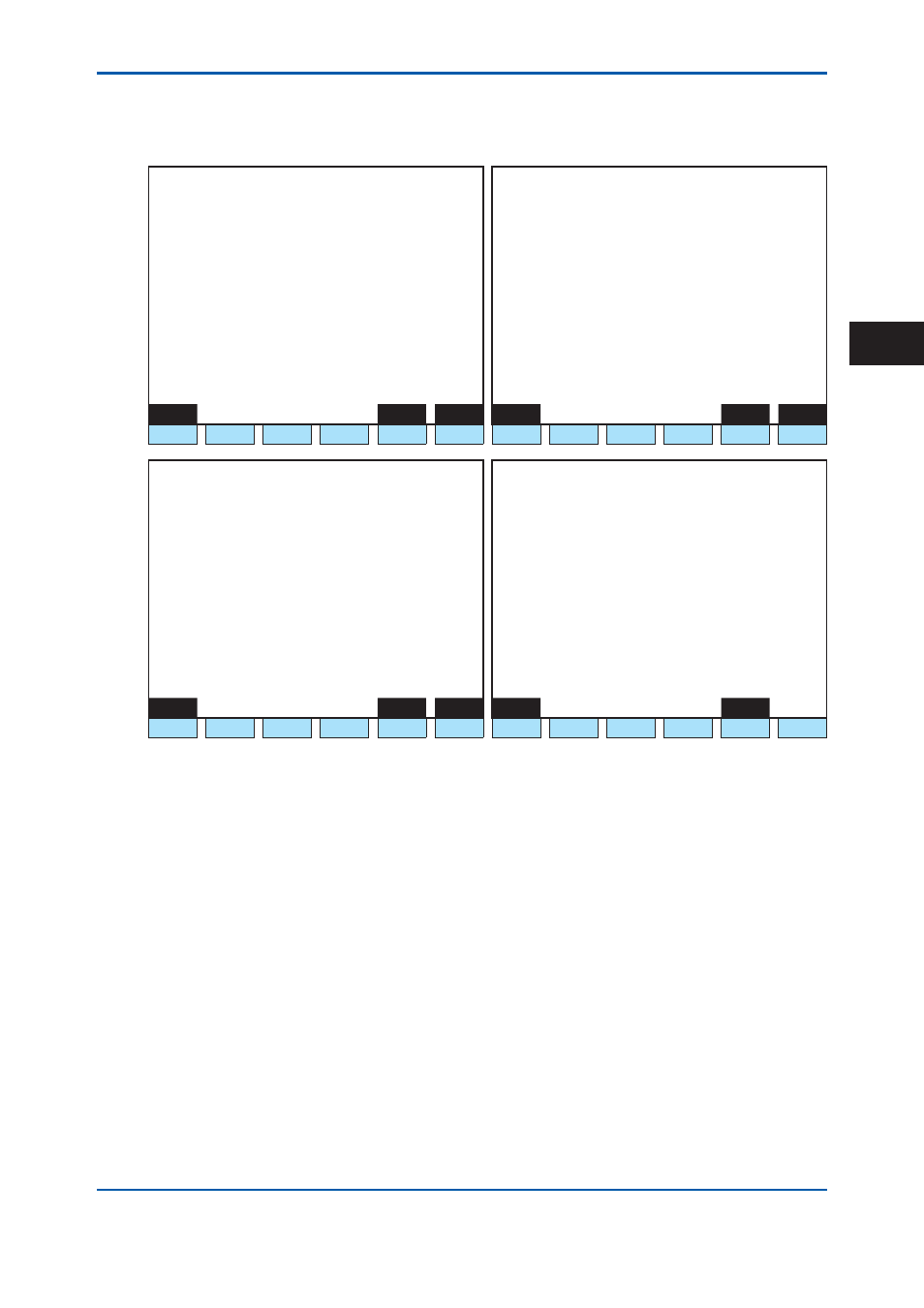
5.4.23 SYS
Setup
Valve set
1 1 / 1 1 / 2 2
1 5 : 1 5 : 4 5
SYS Setup
(1/4)
1 1 / 1 1 / 2 2
1 5 : 1 5 : 4 5
SYS Setup
(2/4)
SYS # 1 Oven #
1 Valve
SYS # 1 Oven #
1 Det
>
- Valve 1-1 Yes
>
- Det 1-1 ( TCD ) Yes
- Valve 1-2 - - -
- Det 1-2 ( TCD ) - - -
- Valve 1-3 - - -
- Valve 1-4 - - -
- Valve 1-5 - - -
- Valve 1-6 - - -
- Valve 1-7 - - -
Menu
SYS#
Oven#
Menu
SYS#
Oven#
F1
F2
F3
F4
F5
F6
F1
F2
F3
F4
F5
F6
1 1 / 1 1 / 2 2
1 5 : 1 5 : 4 5
SYS Setup
(3/4)
1 1 / 1 1 / 2 2
1 5 : 1 5 : 4 5
SYS Setup
(4/4)
SYS # 1 Oven #
1 EPC
SYS # 1 Oven #
1 Oven
>
- Carrier 1-1 - - -
>
- Oven 1 ( Isothermal ) Yes
- Carrier 1-2 - - -
- Oven 2 ( Program
) No
- Utility 1-1 - - -
- Oven 3 ( Not provided ) - - -
- Utility 1-2 - - -
- Utility 1-3 - - -
- Utility 1-4 - - -
Menu
SYS#
Oven#
Menu
SYS#
F1
F2
F3
F4
F5
F6
F1
F2
F3
F4
F5
F6
Figure 5.106
Example of SYS setup screen
F1 (Menu):
Displays the Table menu screen.
F5 (Sys #):
Specifi es a SYS number.
F6 (Oven #): Specifi es an Oven number.
Press F5 (SYS#), and “SYS No.:” is displayed in the second line below.
Use the numeric keypad to input the number and press the Set/Ent key, and the SYS contents of
the number is shown.
Press F6 (Oven#), and “Oven No.” is displayed in the second line below.
Use the numeric keypad to select the number and press the Set/Ent key, and it is refl ected in the
second line above, and the valve set of the specifi ed oven is completed.
Point a cursor to the valve and press the Set/Ent key, and options are displayed in the second
line below.
Select either Yes or NA (NA is default)
Not installed valves are displayed as ----.
When any of the Not installed valves is used by other SYS, **** is displayed.
2nd Edition : May 11, 2012-00
5