The analog output card is labeled “ao – Yokogawa GC8000 Process Gas Chromatograph User Manual
Page 147
<2. Installation, Piping, and Wiring>
2-30
IM 11B08A01-01E
1
2
3
4
5
6
7
8
9
10
11
12
1
2
3
4
5
6
7
8
9
10
11
12
V1 +
V1 -
TxD1 +
TxD1 -
RxD1 +
RxD1 -
24V DC
RS-422
(L)
V2 +
V2 -
TxD2 +
TxD2 -
RxD2 +
RxD2 -
24V DC
RS-422
(C), (D)
(D)
*1
*1
*3
*1 *2
5 V +
6 V -
1 RxD +
2 RxD -
3 TxD +
4 TxD -
5 V +
6 V -
1 RxD +
2 RxD -
3 TxD +
4 TxD -
D-sub9 pin
male
D-sub9 pin
male
Communication converter *4
K9806AS (rack-mounted type)
K9806AT desk-top type)
*4: Two communication converters are required for 2ch.
RS-232C
RS-232C
(L)
*1 *2
For 2ch
*1: This is not used for FM-Y.
*2: The ground wire is connected to the earth bar.
*3: The ground wire is connected to the earth terminal on site.
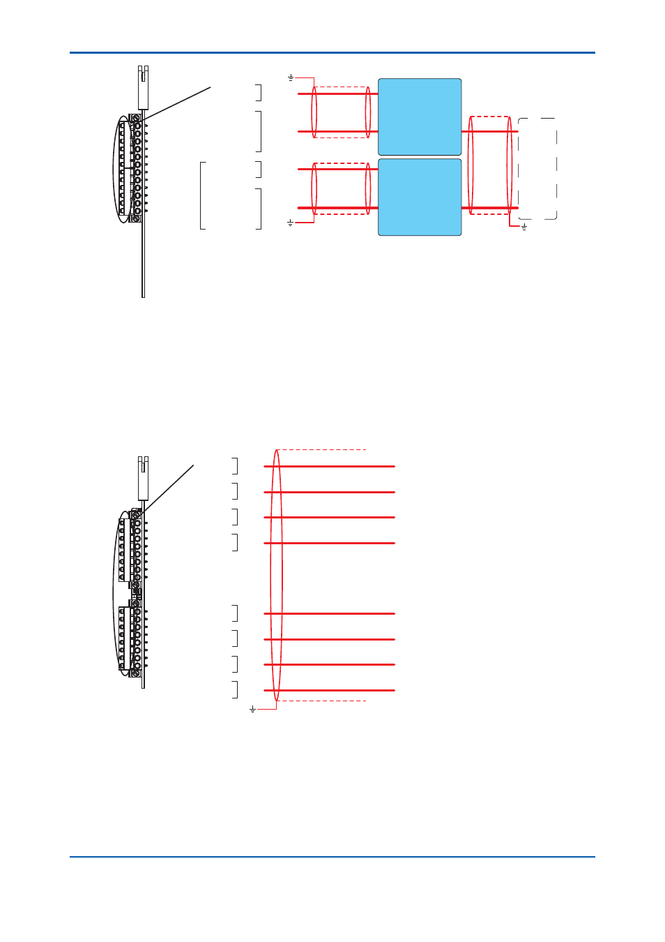
Figure2.27
Wiring for serial communication cards
The serial communication card is labeled “COM”.
The external I/O cutoff output (power cutoff signal) (L) is also wired.
The shield is grounded at the earth bar in Figure 2.22. Remove the cover on the upper right of the
electronics section and perform wiring.
Analog output (system isolation) (Code: 1) and analog output (channel
isolation) (Code: 2) (J)
1
2
3
4
5
6
7
8
11
12
13
14
15
16
17
18
1
2
3
4
5
6
7
8
11
12
13
14
15
16
17
18
AO1
AO2
AO3
AO4
AO5
AO6
AO7
AO8
+
-
+
-
+
-
+
-
+
-
+
-
+
-
+
-
(J)
(J)
(J)
(J)
(J)
(J)
(J)
(J)
*1
*1: The ground wire is connected to the earth bar.
Figure 2.28
Wiring for an analog output card
The analog output card is labeled “AO”.
2nd Edition : May 11, 2012-00