App.d-14, Alarm – Yokogawa GC8000 Process Gas Chromatograph User Manual
Page 459
App.D-14
IM 11B08A01-01E
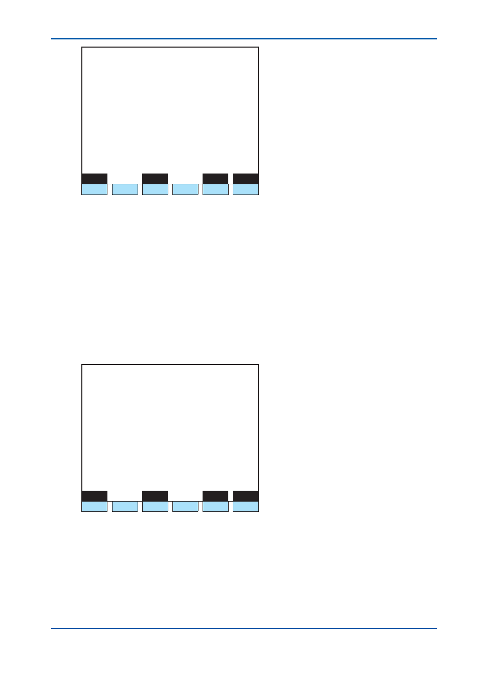
1 1 / 1 1 / 2 2
1 5 : 1 5 : 4 5
D/O Setup
Slot # 1 DO # 1
>
- Process assign Operation mode
- GCM number 1
- Operation mode Run
Menu
Status
Slot#
DO#
F1
F2
F3
F4
F5
F6
Figure 17 Process Specifi cation: Operation Mode (D/O Setting Screen on GC-HMI EtherLCD)
Alarm
The Alarm function of D/O is a function to send out information that an alarm, which level is
specifi ed for all GCMs or each GCM, is activated. The contact output is turned On when an alarm
of the level set on the D/O setting screen is generated. The contact output is turned Off when the
alarm is cleared.
To set an alarm for all GCMs, specify “0” for the GCM number. To set an alarm for each GCM,
specify the relevant GCM number.
One or more of the following three types of alarm level can be set for each contact point.
• Alarm level 1: No. 1 to 200
• Alarm level 2: No. 201 to 400 (including component alarm No. 291 to 294)
• Component alarm No. 291 to 294 (part of Level 2 alarm)
For the details of alarms, see 7.1.
1 1 / 1 1 / 2 2
1 5 : 1 5 : 4 5
D/O Setup
Slot # 1 DO # 1
>
- Process assign Alarm
- GCM number 1
- Alarm level 1 On
- Alarm level 2 On
- Composition Alarm
On
Menu
Status
Slot#
DO#
F1
F2
F3
F4
F5
F6
Figure 18 Process Specifi cation: Alarm (D/O Setting Screen on GC-HMI EtherLCD)
The Component alarm is a level 2 alarm that can be registered by users.
An alarm is activated when a measurement of the peak specifi ed for all streams or each
stream exceeds the upper limit or falls below the lower limit. The alarm keeps going off until the
measurement returns within the specifi ed range.
Up to 32 alarms can be set for each GCM.
To cover the peak numbers of all streams, specify “99” for the stream number. To cover the peak
numbers of each stream, specify the relevant stream number.
2nd Edition : May 11, 2012-00