App.d-6 – Yokogawa GC8000 Process Gas Chromatograph User Manual
Page 451
App.D-6
IM 11B08A01-01E
When “99” is Set for Output Stream Number (with Stream Identifi cation Signal)
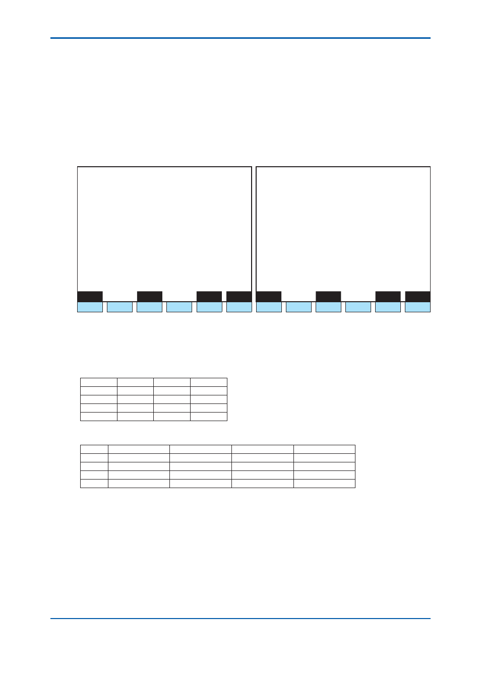
Select Normal output for the AO chromatogram on the A/O setting screen to open the analog
hold output (analysis result output) setting screen (Figure 5.37).
To output an analysis value for all the streams that belong to the GCM, specify the GCM number
and set the output stream number to “99.” Next, specify the peak number as well as the upper
and lower limits of the partial range. The #2 output peak setting is invalid.
When “99” is specifi ed for the stream number, be sure to use contact output as a stream
identifi cation signal.
For an example of settings in the case where a stream identifi cation signal is used, see 6.1.3.
1 1 / 1 1 / 2 2
1 5 : 1 5 : 4 5
A/O Setup
(1/2)
1 1 / 1 1 / 2 2
1 5 : 1 5 : 4 5
A/O Setup
(2/2)
Slot #
1 AO # 1
Slot #
1 AO # 1
>
- GCM number 1
>
- #2 Output stream ** ( )
- AO Chromatogram
Normal output
#2 Output peak ** ( )
- #1 Output stream 99 ( )
- #2 Percent span offset 1.000
#1 Output peak 1 ( )
- #2 Percent zero offset
0.000
- #1 Percent span offset 1.000
- #1 Percent zero offset
0.000
Menu
Status
Slot#
AO#
Menu
Status
Slot#
AO#
F1
F2
F3
F4
F5
F6
F1
F2
F3
F4
F5
F6
Figure 7 Analog Hold Output: Analysis Result of All the Streams that Belong to the GCM (A/O Setting
Screen on GC-HMI EtherLCD)
Table 6 and 7 show an example of analog output settings.
Figure 8 illustrates respective actions.
Table 6
Conditions of Peaks for Streams
Stream 1 Stream 2 Stream 3
Peak 1
Exist
Exist
Exist
Peak 2
Exist
None
Exist
Peak 3
Exist
Exist
None
Peak 4
Exist
None
Exist
Table 7
Example of Analog Output Settings
Output stream #1 Output peak #1 Output stream #2 Output peak #2
A/O1
99
1
None
None
A/O2
99
2
None
None
A/O3
99
3
None
None
A/O4
99
4
None
None
2nd Edition : May 11, 2012-00