Caution – Yokogawa GC8000 Process Gas Chromatograph User Manual
Page 404
<6. Maintenance>
6-51
IM 11B08A01-01E
L9805ZF
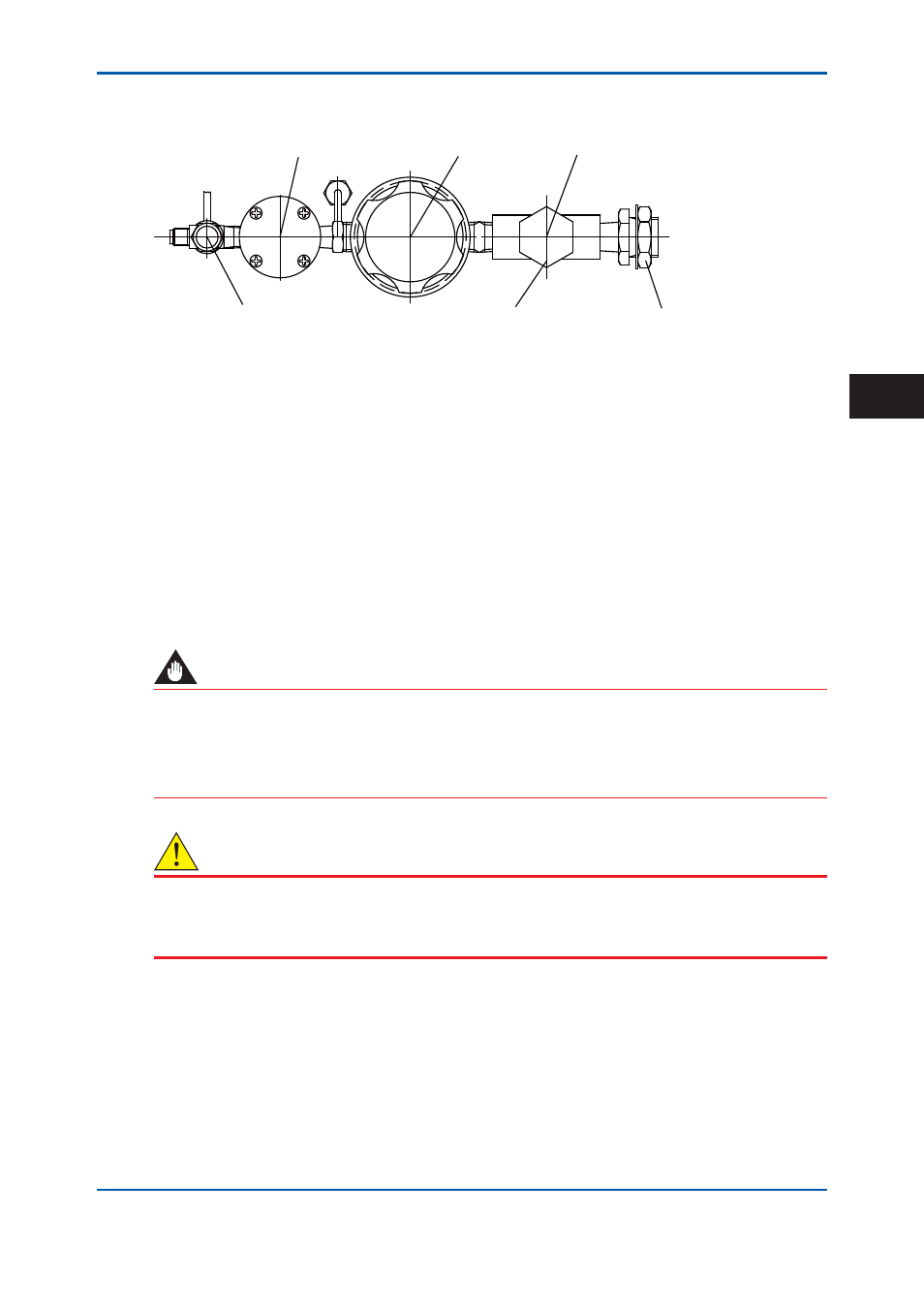
Regulator valve for samples (Diaphragm: Tefl on, Liner: SUS)
L9862AB Filter
Needle valve
Stream switching valve
Regulator for samples
Filter
Cap nut
Nut
Figure 6.44
Example of Sample Processing System (May contain a Stop Valve depending on the
system)
Filter element
(1) Stop the operation. (See “3.3.4 Stopping operation” for this procedure).
(2) Turn off the supply of the sample.
(3) If the sample is liquid, purge the sample line with the purge gas (nitrogen gas or instrument
air).
• When the stream switching valve is a pneumatic valve, change the analyzer status to
Manual and turn on the stream switching valve on the sample line to let the purge gas fl ow
in.
• When the stream switching valve is a stop valve, close all the stop valves and open the stop
valve on the sample line to let the purge gas fl ow in.
(4) Close all the stream switching valves.
IMPORTANT
• During the purge, purge gas may fl ow into the sample return line, causing pressure
fl uctuation.
Prepare the sample return line and collection tank, if necessary.
• Prepare the sample return line so that the sample does not return.
CAUTION
The isothermal oven is extremely hot after turning off the power immediately. Keep the purging
air supplied for more than an hour after turning off the power. Keep hands away from the oven
components.
(5) Remove the cap nut (see Figure 6.45).
(6) Replace the internal fi lter element and the gaskets with a new one.
(7) Firmly tighten the cap nut.
(8) Confi rm that there are no leaks.
L9862AG Filter
element
L9862AC Gasket
1
2nd Edition : May 11, 2012-00
6