Installation, piping, and wiring, Figure 2.19 – Yokogawa GC8000 Process Gas Chromatograph User Manual
Page 140
<2. Installation, Piping, and Wiring>
2-23
IM 11B08A01-01E
.
L
N
ELECTRIC
CIRCUIT
L
3
N
HEATER
ANNUNCIATOR
L
N
ELECTRIC
CIRCUIT
L
N
HEATER
L
N
*
*
HEATER
2 1
COM
NO
NC
6 5 4
COM
NO
NC
SYSTEM ALARM
3 2 1
COM
NO
NC
6 5 4
COM
NO
NC
L
N
HEATER
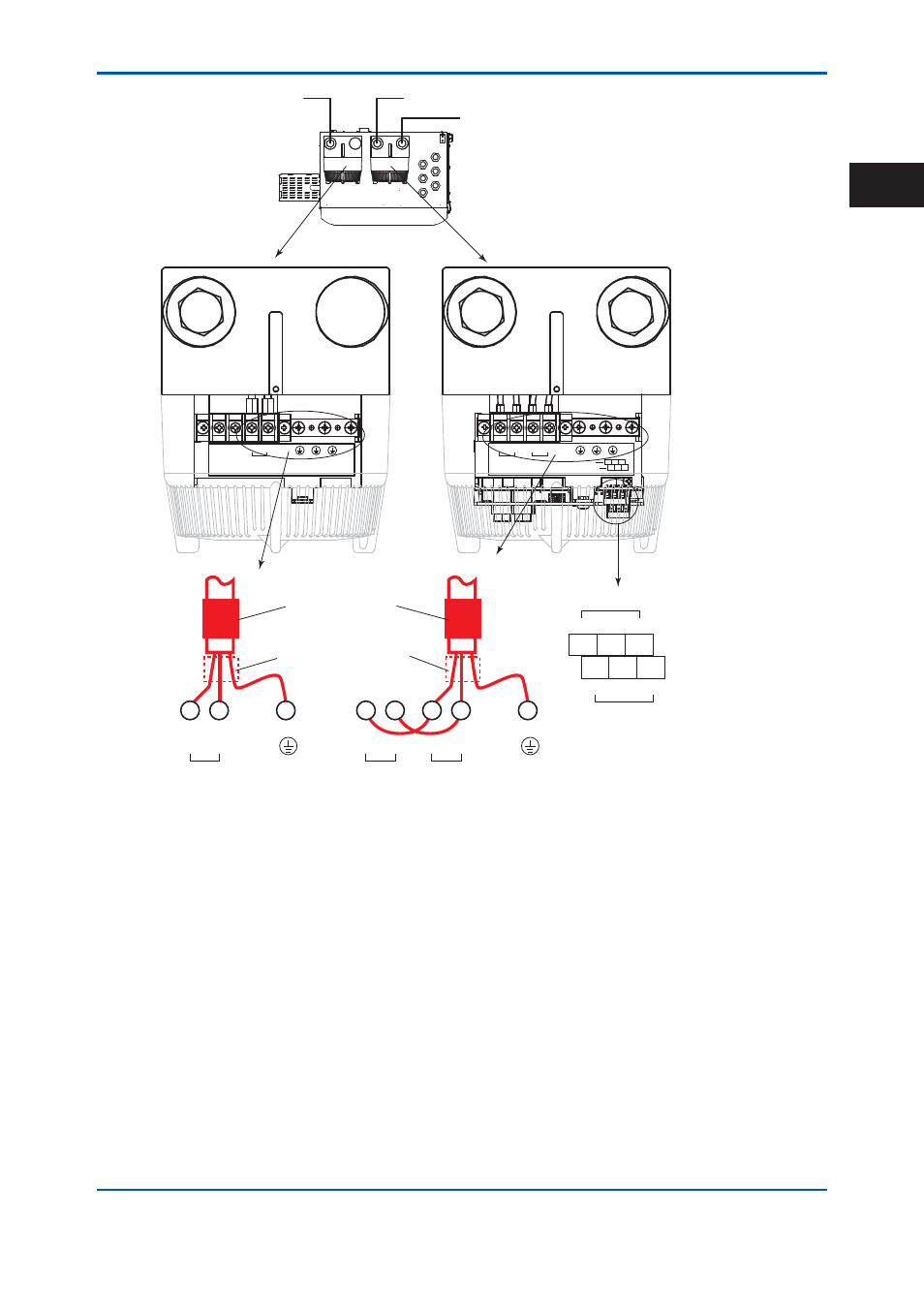
Top view of the protection system
without the cover
Power supply for electric circuit and heater
Contact output for system alarm 1
Contact output for annunciator
Power supply for heater
Front view
Contact for annunciator
Contact for system alarm 1
Ferrite core
(provided for
ATEX and IECEx)
Position when the cable
O.D. exceeds 13 mm
Power supply for electric circuit and heater
Power supply for heater
*: Grounding is possible from any
one of the three terminals.
Figure 2.19
2nd Edition : May 11, 2012-00
2