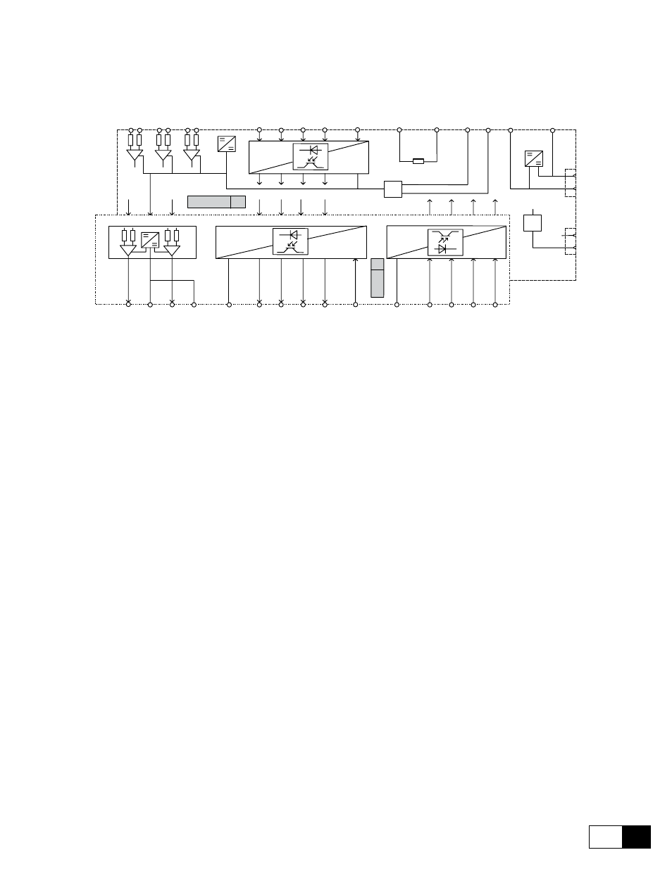
11 engineering notes, Potentials of the regulator section, Figure 4.11.1: potentials of the regulator section – GE Industrial Solutions DV-300 DC Drive Users Manual User Manual
Page 75
DV-300 Adjustable Speed Drives
——— WIRING PROCEDURES ———
4
31
4.11 ENGINEERING NOTES
TBO
Analog outputs
1
2
1
2
3
4
Digital outputs
1
2
3
4
5
6
7
8
9
10
Supply
Digital inputs
15
11
12
13
14
1
2
3
4
1 2
3 4
5 6
Analog inputs
12
13
14
15
16
Enables
11
XE
2
7
2
19
18
+
2
4
V
0
V
2
4
9
0
V
1
0
+
1
0
V
-
1
0
V
7
8
Reference
Supply dig. I/O
R-TPD3
XE
1
7
9
+ 15 V
+ 5 V
± 15 V
Sinusencoder
Digitale
encoder
0
V
0 V
Figure 4.11.1: Potentials of the regulator section
potentials of the regulator section
The potentials of the regulator section are galvanic divided from the power section. Figure 4.11.1 shows their
connection.
- The analog inputs are designed as differential.
- The enables are isolated from the regulation via optoisolators. The terminals 12 to 15 have terminal 16 as a
common reference potential.
- The internal potential 0V is connected to terminal 11. In the majority of the cases the interference suppres-
sion is decreased!
- The regulation card puts at your disposal the following power supplies, which have a common reference
point:
+ 10V and - 10V for the reference
+ 24V for the power supply of the digital inputs and outputs
+ 5V for the encoder power supply
- The analog outputs are divided from the internal potential through a differential amplifier. The two outputs
of the option card have the same potential (terminal 22 and 24 of 6KCV300TBO option card). When the
6KCV300TBO option card is used, the potential of the analog outputs are divided. For a better interference
suppression and for the “cleaning” of the output signals, the terminals 22 and 24 of the 6KCV300TBO option
card are directly ground connected (terminal 10 and /or 20 of the R-TPD3 card) or via a 0.1µF/250V capacitor.
- The digital outputs have the same potential (terminal 37) but they are divided from the regulator internal
potential via optoisolators. In order to use the outputs, it is necessary to connect a power supply voltage to
the terminal 30.
- The digital inputs are divided from the regualtor through optoisolators. The terminals 31 to 34 have terminal
37 as a common potential.