1 enables – GE Industrial Solutions DV-300 DC Drive Users Manual User Manual
Page 131
DV-300 Adjustable Speed Drives
——— FUNCTION DESCRIPTION ———
6
3
6.1 ENABLES
The following hardware enables are always required irrespective of whether the device is to be controlled via
the terminal strip, the keypad or the serial interface.
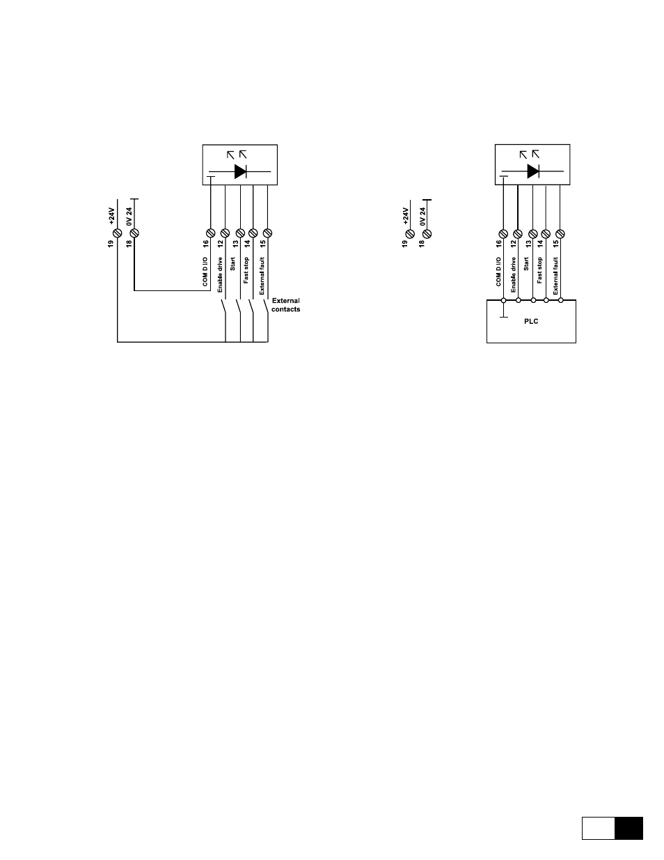
Figure 6.1.1 Enables via potential free contacts and PLC
- Figure 6.1.1 show the connection principle
- The enable signals are activated via a +15 ... 30 V voltage at the appropriate terminals.The inputs are pro-
tected against reverse polarity.
- Negative voltage, 0 V and a missing signal are interpreted as disable signals.
- The reference point for the enable signals is terminal 16.
- When using an operator keypad/serial interface (Mains Command = Digital), both the signals on the ap-
propriate terminals and the corresponding commands on the keypad/serial interface are necessary. If an en-
able is removed via a signal on the terminals, the appropriate command must be sent via the keypad/serial
interface in addition to the signal on the terminal in order to restart the drive.
There are four types of enable signals that have a different effect on the behavior of the DV-300 converter.
- Enable drive
enables the entire converter
- Start
enables the regulation
- Fast stop
sets the speed reference value immediately to zero so that the motor is stopped as quickly
as possible
- External fault
incorporates external fault condition into the enable