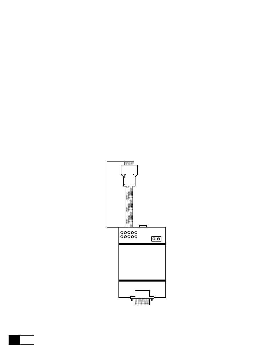
7 digital encoder interface 6kdv300des, 1 description, Figure 4.7.1.1: 6kdv300des card – GE Industrial Solutions DV-300 DC Drive Users Manual User Manual
Page 60: 6kdv300des
GEI-100332Ga
——— WIRING PROCEDURES ———
4
16
4.7 DIGITAL ENCODER INTERFACE 6KDV300DES
4.7.1 Description
The option card 6KDV300DES has been projected to adapt, to separate galvanically and to connect a digital
encoder to the input XE1 of the converters DV-300 regulations boards. As standard, this input is arranged for
the connection of an analog encoder.
The card 6KDV300DES will be fixed externally to the drive by the mounting rail DIN EN 50 022-35. The
input female connector XS1 must be connected to the digital encoder using a 9-pole male connector, through a
shielded cable, Tasker c/186 (6 x 2 x 0.22) with a maximal length of 150 m.
The output male connector XS2, provided with shielded cable of 1.5 m, must be connected to the 9-pole con-
nector fitted on the DV-300 regulation card.
Terminals +Venc and 0Venc are needed for the external supply of the digital encoder: the input voltage can
be 15V...24V with open Jumpers S1, S2, S3 (standard delivery conditions), or 5V with closed Jumpers S1, S2,
S3.
S4 jumper is used to cut out the canal C (no impulse) from the test of encoder loss. S4 closed = canal C included,
S4 open = canal C cut out.
The jumper SH is mounted on condition of standard delivery; it must be cut only in case of the shield side en-
coder is connected to the chassis of the motor, to avoid the moulding of ground ring.
For converter operation with the 6KDV300DES card it is necessary to set the jumper S5, S6 on the regulation
board in position A.
1
3
5
7
9
4
2
6
8
SH
XS1
+V
enc
0V
enc
Cable
Lengt
h
=
1.5m
6KDV300DES
XS2
Figure 4.7.1.1: 6KDV300DES card