Figure 6.12.2.1: analog input – GE Industrial Solutions DV-300 DC Drive Users Manual User Manual
Page 199
DV-300 Adjustable Speed Drives
——— FUNCTION DESCRIPTION ———
6
71
S
+
-
6
5
Volts
Ref_3-
Ref_3+
HW
input
type
S
+
-
4
3
Volts
Ref_2-
Ref_2+
HW
input
type
From digital reference
setting
From digital reference
setting
+
-
2
1
Volts
Ref_1-
Ref_1+
HW
input
type
From digital reference
setting
Window comparator
F
F
F
Input 3 type
-10V ... +10V
Offset input 3
0
Scale input 3
1
Tune value inp 3
1
Select input 3
OFF
Input 2 type
-10V ... +10V
Offset input 2
0
Scale input 2
1
Tune value inp 2
1
Select input 2
OFF
Auto tune inp 3
0
Auto tune inp 2
0
Input 1 type
-10V ... +10V
Offset input 1
0
Scale input 1
1
Tune value inp 1
1
Auto tune inp 1
0
Input 1 filter
0 ms
Select input 1
Ramp ref 1
Input 1 compare
0
Input 1 cp error
0
Input 1 cp delay
0 ms
Input 1 cp match
An in 1 target
An in 2 target
An in 3 target
Select input 1
Ramp ref 1
Select input 2
OFF
Select input 3
OFF
S
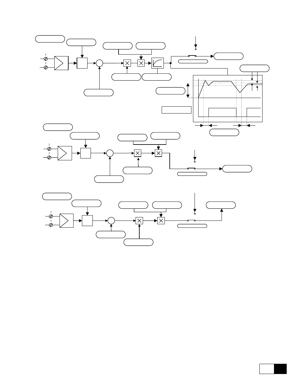
Figure 6.12.2.1: Analog input
Analog Input 1 window comparator
This function allows to signal the match of a programmable value on analog input 1.
Input 1 compare
Sets the level for the comparator.
Input 1 cp error
Defines a tolerance window around Input 1 compare.
Input 1 cp delay
Millisecond delay during the switching from the low to the high level Input 1 cp match.
Input 1 cp match
Signalling output of the video comparator.
It can be read through a Field Bus LAN or digital output.
High
Analog input 1 value is within the comparation window.
Low
Analog input 1 value is out the comparation window.