Winder/unwinder control with dancer, Machine data, Input/output – GE Industrial Solutions DV-300 DC Drive Users Manual User Manual
Page 289
DV-300 Adjustable Speed Drives
——— FUNCTION DESCRIPTION ———
6
161
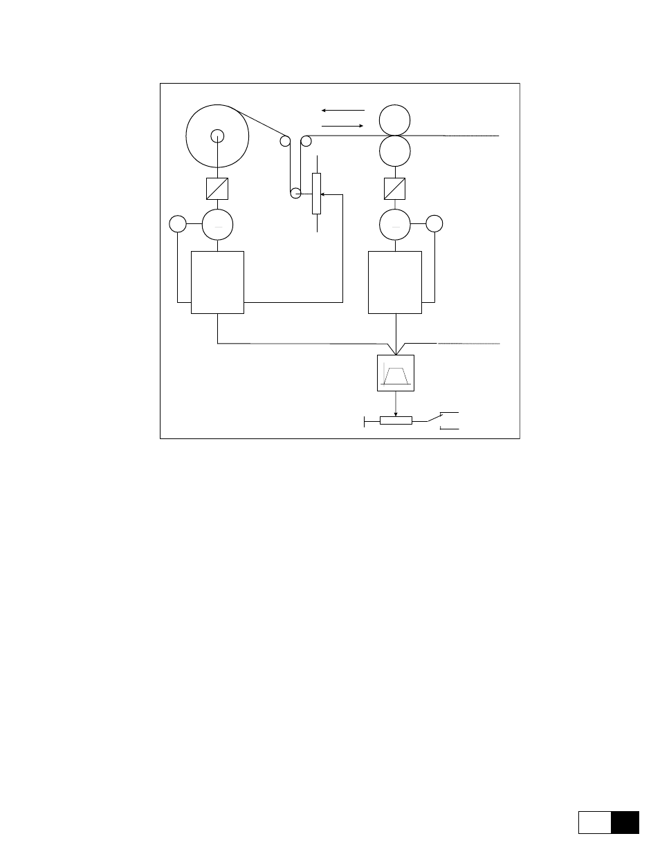
Winder/Unwinder control with dancer
M
M
E
-10V
+10V
Feed-forward
Feed-back
5Kohm
+10V
-10V
E
R
(Internal ramp
master drive)
Line speed
reference
Forward
Reverse
DRIVE
DRIVE
Winder/unwinder
Dancer
Forward
Reverse
Nip-roll
Figure 6.16.3.10: Winder/Unwinder control with dancer
Machine data:
Max. line speed =400m/min
Rated speed of the motor winder/unwinder Vn = 3000rpm
Max. diameter of the winder/unwinder = 700mm
Min. diameter of the winder/unwinder = 100mm
Reduction ratio motor-coil = 0.5
One pitch dancer
Dancer stroke from the lower limit switch to the position of electric 0 = 160mm
The drive of the winder/unwinder must be sent the analog signals regarding line speed and the position of the
dancer (whose potentiometer will be supplied between the terminals -10V... +10V) and the digital commands
regarding the enabling of the PID control.
The regulator output will be sent to the speed reference 1.
Drive setting: (below are only the parameters regarding the PID function)
Input/output
Set Analog input 1 as input for the cursor of the dancer.
Analog input 1 / Select input 1= PID Feed-back
Set Analog input 2 as line speed input (feed- forward).