GE Industrial Solutions DV-300 DC Drive Users Manual User Manual
Page 302
GEI-100332Ga
——— FUNCTION DESCRIPTION ———
6
174
The LINK source must be associated to PI output PID [n
0
771]:
Source link 1 = 8192 + 771 = 8963
The LINK destination must be associated to the value of the integral component= parameter PI I gain PID [n
0
764]:
Destination link 1 = 8192 + 764 = 8956
The multiplier factor must be set to the value defined by the functioning tests above mentioned.
Mul gain link 1 = 40
It will be necessary to set:
Div gain link 1 = 1000
*
Input max link 1 = 1000
*
Input min link 1 = 100
**
Input offset link 1 = 0
Output offset link 1 = 0
Input absolute link 1 = OFF
*
The value 1000 is defined by PI top lim which will be in this case = 1 (correspondent to a maximum value
of PI output PID = 1000).
**
The value 100 is defined by PI bottom lim which will be in this case = 0.1 (correspondent to a minimum
value of PI output PID = 100).
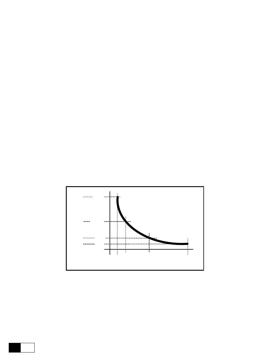
With this configuration at minimum diameter it will correspond an integral gain = 40% and at maximum diameter
it will correspond to an integral gain = 4%, between the two setpoints the gain will change with an hyperbolic
characteristic.
P
I
I
gain
PID
100
1000
PI
output
PID
40%
4%
Fmax
F
20%
PI I gain PID =
(
Fo / Fatt x KI
)
[KI = 40%]
Fo
100
1000
200
500
8%
500
200
Figure 6.16.3.16: Relation between PI I gain PID and PI I output PID
The value of PI I gain PID will be displayed in the relative parameter of the submenu PI controls.
If necessary, using the LINK 2, it is possible to modify, dynamically, the proportional gain P gain PID.