Control of the speed reference – GE Industrial Solutions DV-300 DC Drive Users Manual User Manual
Page 316
GEI-100332Ga
——— FUNCTION DESCRIPTION ———
6
188
Control of the speed reference
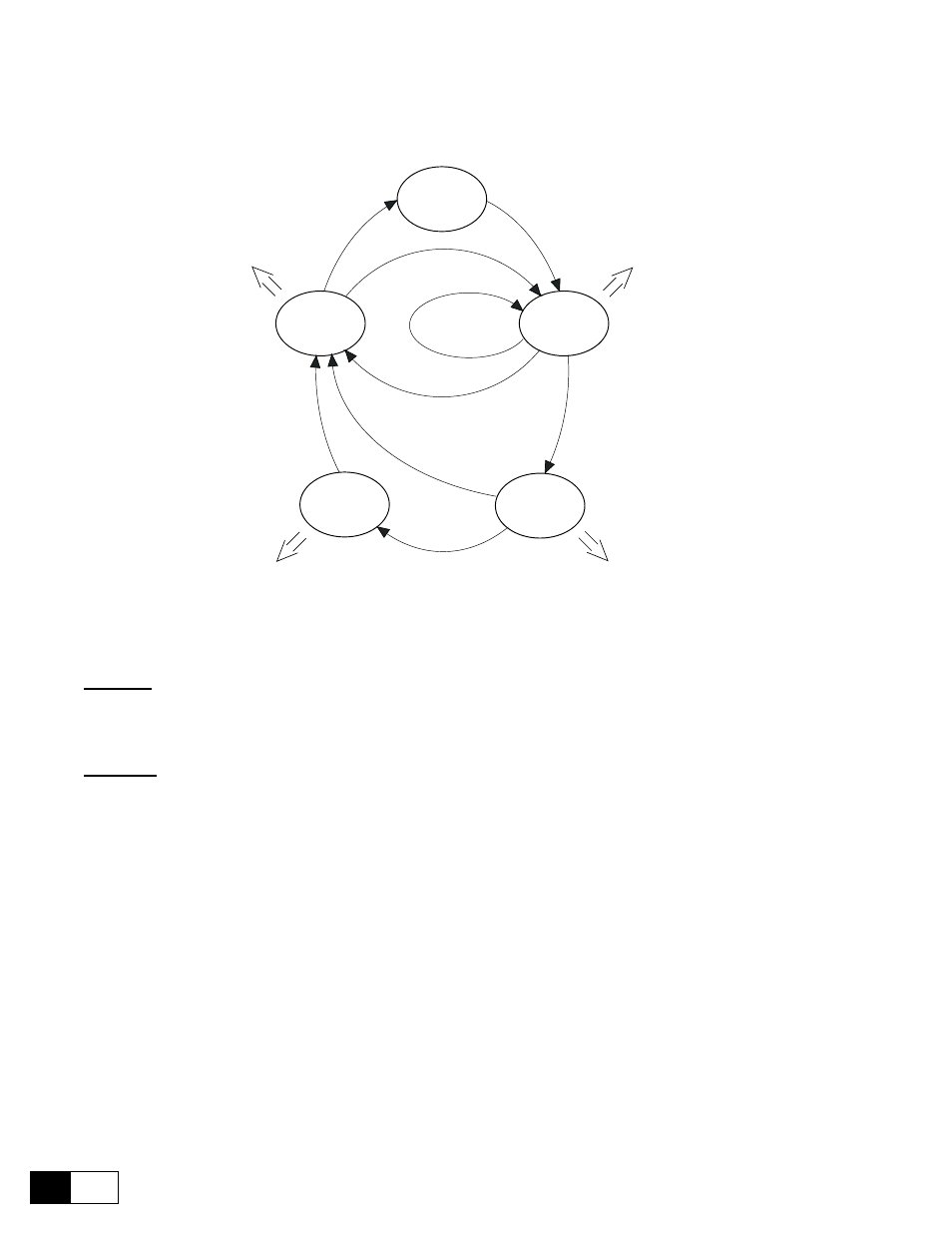
In order to calculate the speed reference during the different functioning phases of the machine, a status logic
has been developed. The status sequence and the operativeness is described in the figure 6.17.3.
Status 1
(default)
Status 2
Status 3
Status 4
Status 5
Start
(drive
)
=
1
Start (drive) = 1
Start (drive) = 0
Start
(drive)
=
0
Start (drive) = 0
Speed match = 1
Speed match = 0
Spee
d
0
thr
=
1
Int acc time = 0
Int dec time = 0
Int offset acc time = Offset acc time
Int w offset = W offset
Int acc time = Spd match acc
Int dec time = 0
Int offset acc time = 0
Int w offset = 0
Int acc time = 0
Int dec time = Spd match dec
Int offset acc time = 0
Int w offset = 0
Int acc time = 0
Int dec time = 0
Int offset acc time = 0
Int w offset = W offset
Figure 6.17.3: Operative sequence of the functioning status
Status 1:
Default status, this system condition is given when the drive is in a Stop condition. The speed reference is zero.
Status 2:
The system reaches this status when the Start command is given.
When the line is stopped, the initial phase reference W offset is assigned with the ramp time Offset acc time.
When the line is started, the motor speed reference follows its profile with a value corresponding to:
W reference = ± Line speed x (Minimum diameter ÷ Roll diameter) ± (W gain % + W offset)
the sign of:
± Line speed x (Minumum diameter ÷ Roll diameter)
is positive if Wind/unwind = winder
is negative if Wind/unwind = unwinder
the sign of:
± (W gain % + W offset)
is usually positive, it could be changed only if during the acceleration or deceleration phases a torque inver-
sion is required.
The polarity of W reference will be further inverted if Winder side = 1
(winding/unwinding down).
If during a Status 1functioning period the system receives a Stop command (Start drive = 0), the Status 5 is
forced.