7 others tuning, Flux / if curve tuning (flux / if curve), Figure 5.3.7.1: curve convertion flux/current – GE Industrial Solutions DV-300 DC Drive Users Manual User Manual
Page 125
DV-300 Adjustable Speed Drives
——— CONVERTER OPERATION ———
5
49
5.3.7 Others tuning
Flux / if curve tuning (Flux / if curve)
The function of this curve is to model the real flux of the motor. The flux model allows the control of torque
current to better relate to torque. The figure below describes the relation between flux and flux current in condi-
tions of Flux /if curve defined and not defined.
n
ote
!
The field current (previous section) and the output voltage tunings (next section) must be carried
out when a Voltage control is required, whether the relevant flux curve has been defined or not.
The tunings scale is the following:
- Field current regulator
- Flux/ if curve tuning (Flux / if curve)
- Voltage regulator in the field converter
40%
50%
70%
90%
100%
50% Motor nom flux
I field cnst 90
I field cnst 70
I field cnst 40
Flux current
Flux reference
100%
Curve A
Curve B
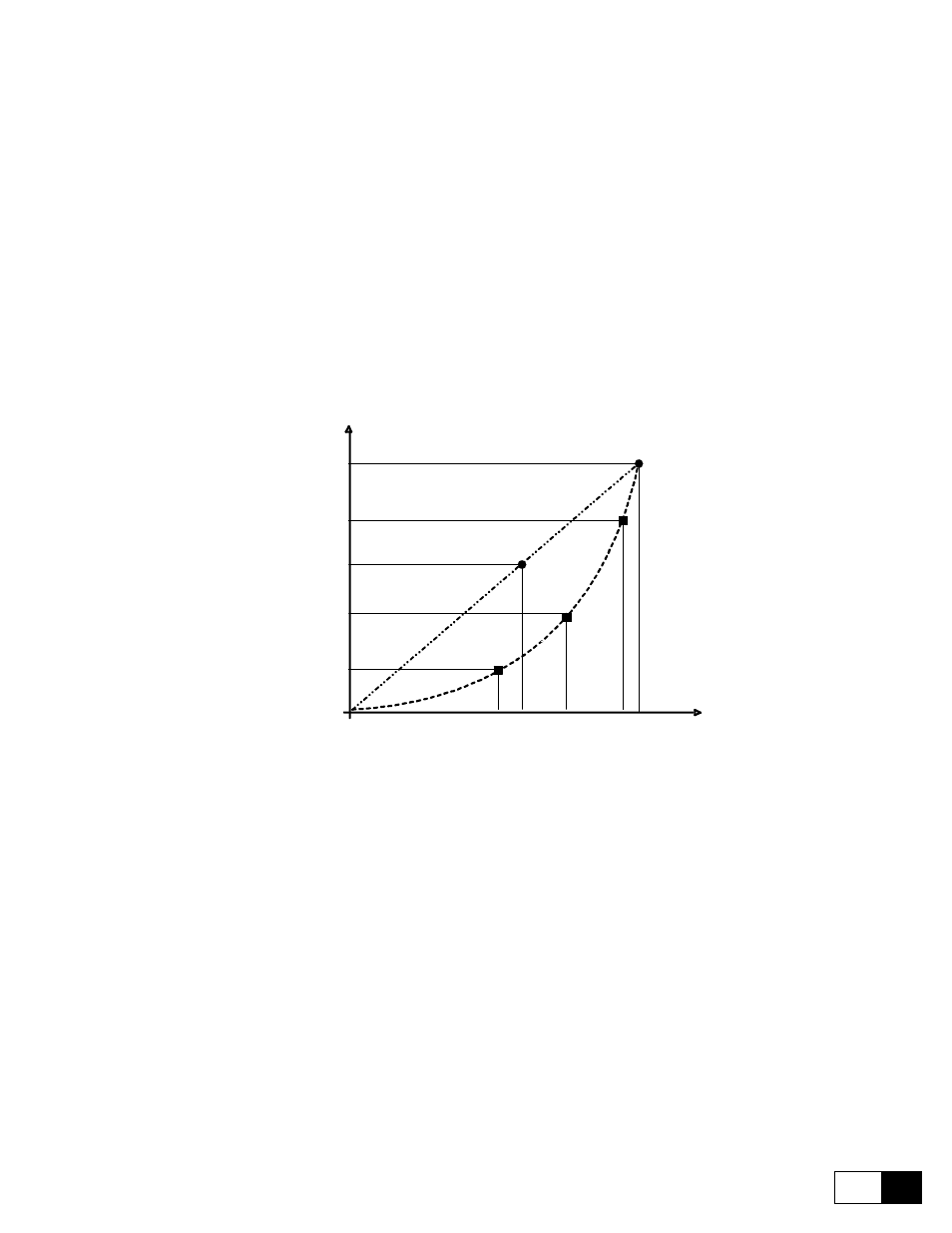
Figure 5.3.7.1: Curve convertion flux/current
Example:
A - With the default setting of the converter, there will be a linear characteristic (Curve A) of the flux current
(Flux current) when the parameter Flux reference changes.
Then:
Flux current max / Flux reference = 100% Flux current / Flux reference = Motor nom flux
Flux current max / Flux reference = 50% Flux current / Flux reference = 50% of Motor nom flux
B- Carrying out the tuning of the flux curve (see below tuning procedure ) the result will be emphasized by
curve B. The values of Flux current will follow a characteristic determined by the real flux percentage Flux
reference, necessary to determinate the circulation of that field current for the connected system.