Flux current min/max, 6 manual tuning of the regulators, Using the test generator – GE Industrial Solutions DV-300 DC Drive Users Manual User Manual
Page 119
DV-300 Adjustable Speed Drives
——— CONVERTER OPERATION ———
5
43
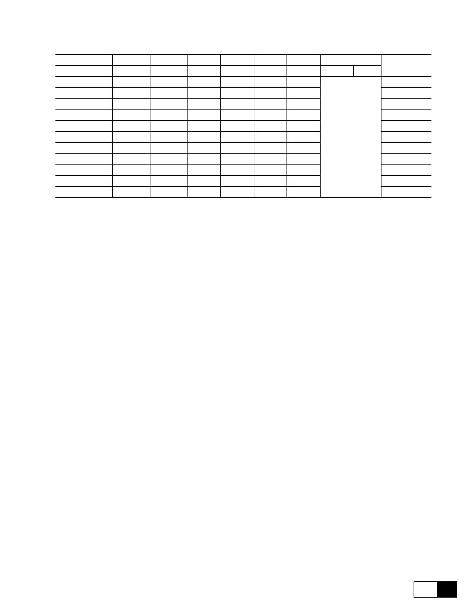
Table 5.3.5.3.1: Tuning resistances of the field current
Switch ohms
168.5 ohm 333.3 ohm 182 ohm 36.4 ohm 845 ohm 1668 ohm
Equivalent
resistance
Nom flux curr
S14-1
S14-2
S14-3
S14-4
S14-5
S14-6
S14-7
S14-8
1.0 A
OFF
OFF
OFF
OFF
OFF
ON
Not used
1688 ohm
2.0 A
OFF
OFF
OFF
OFF
ON
OFF
845 ohm
3.0 A
OFF
OFF
OFF
OFF
ON
ON
560.9 ohm
5.0 A
OFF
ON
OFF
OFF
OFF
OFF
333.3 ohm
9.9 A
ON
OFF
OFF
OFF
OFF
OFF
168.5 ohm
12.9 A
ON
OFF
OFF
OFF
ON
ON
129.6 ohm
14.2 A
OFF
ON
ON
OFF
OFF
OFF
117.7 ohm
17.1 A
OFF
ON
ON
OFF
ON
ON
97.3 ohm
20.0 A
ON
OFF
ON
OFF
OFF
ON
83.1 ohm
24.1 A
ON
ON
ON
OFF
OFF
OFF
69.3 ohm
25.1 A
ON
ON
ON
OFF
OFF
ON
66.5 ohm
DV0032g
Flux current min/max
- Setting in LIMITS / Flux limits menu via the Flux current max and Flux current min parameters as a
percentage of Nom flux curr.
5.3.6 Manual tuning of the regulators
The tuning of the DV-300 converters is factory set to a typical value for the motor size concerned. This nor-
mally ensures satisfactory regulator results. If this setting, however, meets the requirements of the application
concerned, the regulator need not be optimized.
The converter contains the following close-loop control circuits:
- Regulator of the armature current. The auto tuning has to be perform via the R&L Search parameter.
- Speed regulator
- Field current regulator
- Armature voltage regulator
Following is a description of the system suitable to obtain the optimization, if necessary. In order to have a step
function, the internal “Test generator” is used (“SPEC FUNCTIONS” menu). The aim is to obtain a very good
step response.
The analog output can be brought back to the terminal strip, with a sampling time of 2 ms.
using the Test generator
This function generates and makes available some signals with a square wave, with a frequency and a width that
can be set and which can be added to an offset that can be set too. With the parameter Gen access it is possible
to state on which regulator input the signal must be active. Further information can be found in section 6.15.1,
“Test generator”.