7 speed regulation (speed regulat), Figure 6.7.1: speed regulation – GE Industrial Solutions DV-300 DC Drive Users Manual User Manual
Page 159
DV-300 Adjustable Speed Drives
——— FUNCTION DESCRIPTION ———
6
31
6.7 SpEED REGuLATION (SpEED REGuLAT)
Speed Adaptive
and
Speed zero logic
+
+
+
+
+
DV_Srpi
DV_J_comp
DV_Droop_cp
+
+
DV_Spd_fbk
DV_Adp_spd
Speed P/I base
Speed fbk
T
DV_Curr_reg
F
T
+
+
Zero
+
+
Speed Reg P / I
To Current regulator
Load comp
T
Zero torque
Command
P/I regulator includes
anti-windup logic
Speed up
Inertia/Loss comp
Speed droop comp
Speed Limits
F
T current ref 2
0 %
T current ref 1
0 %
Speed reg output
Speed ref 1
0 rpm
Speed ref 2
0 rpm
Speed ref (d)
Actual spd (rpm)
Speed up gain
0 %
Speed up filter
0 ms
Speed up base
1000 ms
Speed P in use
Speed I in use
Speed P
5 %
Speed I
0.5 %
Prop. filter
0 ms
Lock speed I
Not Active
Speed P base
1.536 A/rpm
Speed I base
0.048 A/rpm*ms
Aux spd fun sel
Speed min pos
0 rpm
Speed min neg
0 rpm
Speed min amount
0 rpm
Speed max pos
1750 rpm
Speed max neg
1750 rpm
Speed max amount
1750 rpm
T current ref
Lock speed reg
Enable spd reg
Speed P bypass
10 %
Speed I bypass
1 %
Zero torque
Aux spd fun sel
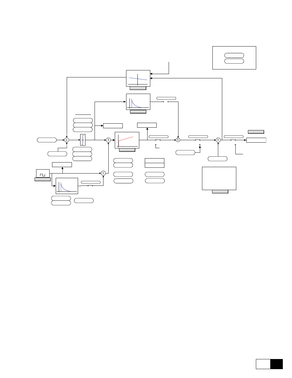
Figure 6.7.1: Speed regulation
The converters of the DV-300 series are provided with a speed regulator circuit that can adapt flexibly to the
requirements of various applications. The device is factory set for PI regulation and regulator parameters that
stay the same throughout the entire speed range.
The following functions are also provided:
- “Speed-up” function in order to avoid oscillations in presence of loads with a high moment of inertia.
- Speed zero logic for regulator behavior when the motor is stopped.
- Speed regulator adaption for optimizing the regulator according to the actual speed or to an external refer-
ence (Adap Reference)..
- Auto capture function of a running motor
- Speed signals
- Droop function for current balancing
For the speed PI regulator diagram block, please refer to “Speed regulator PI part” block diagram on chapter 9.