5 speed draw function, Figure 6.14.5.1: speed draw block diagram – GE Industrial Solutions DV-300 DC Drive Users Manual User Manual
Page 226
GEI-100332Ga
——— FUNCTION DESCRIPTION ———
6
98
6.14.5 Speed Draw function
FUNCTIONS
Speed draw
[1017]
Speed ratio
[1018]
Speed draw out (d)
[1019]
Speed draw out (%)
Parameter description
No.
Value
Standard
Configuration
min
max
Factory
American
Factory
European
Speed ratio
1017
0
+32767
+10000
+10000
Speed draw out (d)
1018
-32768
+32767
-
-
Speed draw out (%)
1019
-200.0
+200.0
-
-
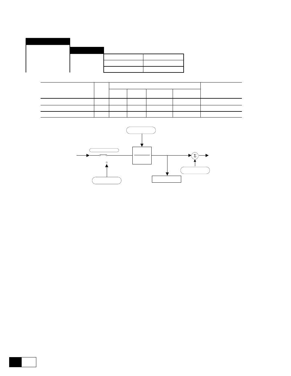
To Max speed limits
Speed ratio
10000
Speed ratio
10000
Speed draw out
Enable ramp
T
From Ramp output
Speed ref 2
0 rpm
Speed ref 1
0 rpm
Figure 6.14.5.1: Speed draw block diagram
This function allows a configurable Speed ratio to be applied to the main reference Speed ref 1.
The Speed ratio range can be set between 0 and 32767 if written in digital form. It can be set from 0 to 20000
(0 to +10V) if assigned via an analog input.
This function is useful in a multidrive system where between the motors is required (see example in figure
6.14.5.2).
The speed resulting value can be read through the Spd draw out parameter via an analog output.
Speed ratio
This parameter determines the speed ratio value.This setting can be done in digital form,
via LAN or through an analog input.
Spd draw out (d)
Speed value in the unit specified by the factor function.
Spd draw out (%)
Speed value as a percentage of Speed base value.