GE Industrial Solutions DV-300 DC Drive Users Manual User Manual
Page 171
DV-300 Adjustable Speed Drives
——— FUNCTION DESCRIPTION ———
6
43
To avoid the overheating of motors which should not run or to avoid the presence of condensa-
tion in motor which work externally ( the field will be used as anti condensation heating).
Enabled
Enabled function
Disabled
Disabled function
Flux reference
Flux/current reference : the 100% corresponds to the Motor nom flux parameter.
With the function Flux / if curve defined, this reference corresponds to the flux reference.
With the function Flux / if curve not defined (default conditions), this reference cor-
responds to the field current reference.
Flux curr (%)
Field current feedback, expressed as percentage of the Motor nom flux parameter.
Out vlt level
Percentage of the maximum output voltage according to the Max out voltage parameter.
This parameter allows the changing of the output voltage in “Voltage control”
(FLUX REGULATION\Flux reg mode).
I field cnst 40
Current value at 40% of flux (see Flux /if curve, paragraph 5.4.5)
I field cnst 70
Current value at 70% of flux (see Flux /if curve, paragraph 5.4.5)
I field cnst 90
Current value at 90% of flux (see Flux /if curve, paragraph 5.4.5)
Set flux / if
Command for the setting of the flux curve according to the setting of I field cnst 40-70-90
parameter. With the defined curve, the meaning of Flux current max/Flux refer-
ence indicates only the flux percentage according to the characteristic of this curve. As
a consequence, the value of the field current will be determined by this characteristic
(see Flux /if curve paragraph 5.4.5).
Reset flux / if
Command for the reset of the flux curve set via command Set flux / if.
With this command the Motor nom flux parameter will be again linearly changed
through Flux current max/Flux reference. (see Flux /if curve paragraph 5.4.5)
Nom flux curr
Rated current I
FN
of the field regulator. In order to improve the behaviour of the regula-
tion, the maximum field current can be reduced by setting the S14 dip-switches (on the
regulation board, see table 2.4.3.2).
Example
Armature:
500 VDC
Field:
230 VDC
102 ADC
0.8 ADC
Drive type:
6KDV3112 (Field current set to 14 Amps = default)
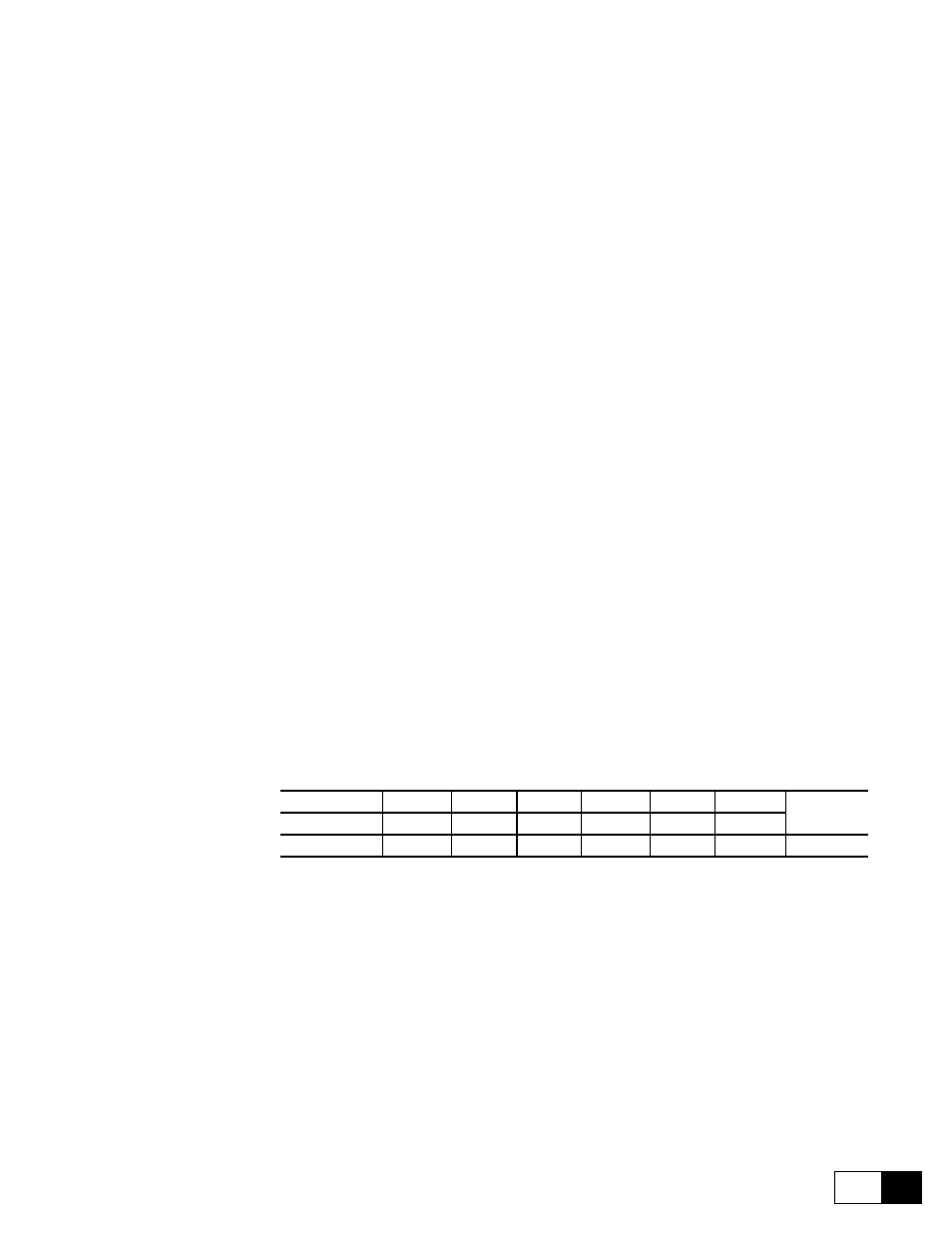
Set the dip switches S14 to decrease the field current from the drive supplied, as below:
Switch ohms
148 ohm 330 ohm 182 ohm 36.4 ohm 845 ohm 1668 ohm Equivalent
resistance
Nom flux curr
S14-1
S14-2
S14-3
S14-4
S14-5
S14-6
1.0 A
OFF
OFF
OFF
OFF
OFF
ON
1668 ohm
GD6111g
Set Nom flux curr parameter to 0.8.
Motor nom flux
Rated field current I
FN
of the connected motor.