GE Industrial Solutions DV-300 DC Drive Users Manual User Manual
Page 270
GEI-100332Ga
——— FUNCTION DESCRIPTION ———
6
142
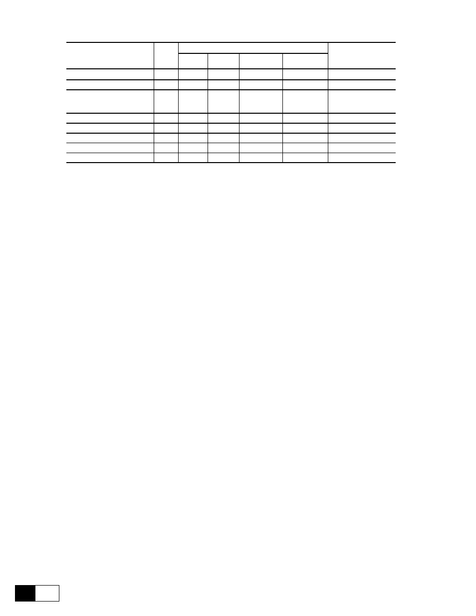
Parameter description
No.
Value
Standard
Configuration
min
max
Factory
American
Factory
European
PID error
759
-10000
+10000
0
0
PID feed-back
763
-10000
+10000
0
0
**
PID offs. Sel
Offset 0 (0)
Offset 1 (1)
762
0
1
0
0
*
PID offset 0
760
-10000
+10000
0
0
**
PID offset 1
761
-10000
+10000
0
0
PID acc time
1046
0.0
900.0
0.0
0.0
PID dec time
1047
0.0
900.0
0.0
0.0
PID clamp
757
-10000
+10000
10000
10000
* This function can be set on a digital programmable input.
** This parameter can be set on an analog programmable input.
PID error
Error reading in the input of the function PID (PID clamp block output).
PID feed-back
Reading of feed-back value from the transducer position (dancer) or tension (load cell).
PID offs. sel
Offset selector added to PID feed-back. This parameter can be set on a digital program-
mable input.
0 = PID offset 0 1 = PID offset 1
PID offset 0
Offset 0 added to PID feed-back. This parameter can be set on analog input , E.g. for
the tension setting when a load cell has to be used as feed-back.
PID offset 1
Offset 1 added to PID feed-back.
PID acc time
Acceleration ramp time value in seconds after the PID offset block.
PID dec time
Deceleration ramp time value in seconds after the PID offset block.
PID clamp
The clamp allows a smooth tension setting of a controlled system winder/unwinder,
when the “calculation of the initial diameter” function cannot be used.
When the drive is enabled, the dancer is at its lower full scale, with PID error at its
maximum value. The motor could accelerate to fast in taking the dancer in its central
position of work.
Setting PID clamp at a value sufficiently low e.g = 1000, at the drive enabling and at
the enabling of Enable PD PID, the value of PID error is limited to 1000 until the
signal coming from the dancer (PID feed-back) does not reach this value. Now PID
clamp is automatically take back at its maximum value corresponding to 10000. The
clamp is kept at 10000 till the next disabling of the drive or of Enable PD PID.
The feed - back input is provided for the analog transducers connection like dancer, with relative potentiometer
or load cell. Nevertheless, it is possible to use this input block as comparison point between two different analog
signals + / - 10V.
Connection to a dancer with potentiometer connected between - 10 and + 10V.
The cursor of the potentiometer can be connected to one of the analog inputs of the drive. Normally it should
be used the analog input 1 (terminals 1 and 2) because it is provided with filter.
The input choosen for that connection must be programmed in the menu I/O CONFIG as PID feed - back. Its
value can be read in the PID feed - back parameter in the PID REFERENCE submenu.
Through PID offset 1 (or PID offset 0), it is possible to carry on the adjustement of the dancer position.