GE Industrial Solutions DV-300 DC Drive Users Manual User Manual
Page 259
DV-300 Adjustable Speed Drives
——— FUNCTION DESCRIPTION ———
6
131
Inp absolute
The input behavior can be determined with this parameter.
OFF
The input quantity is processed with its sign.
ON
The input quantity is processed with a positive sign (absolute
value). It is possible to have a polarity change with the signs
of Mul gain or Div gain.
In order to write SOURCE LINK (1/6) parameter or DESTINATION LINK (1/6) parameter it is neces-
sary to add to the parameter number the offset “8192”
Eg.
RAMP REF 1 “44”
SOURCE LINK (1/2) = 44+8192 = 8236
n
ote
!
The Links are executed with an approximate cycle time of 20 ms. They are not mainly intended
to be used for regulation but to access or connect parameters otherwise not accessible. The
use of Links according to the parameter chosen as a destination involves a CPU overhead
that can slow down the keypad/display operation. Check that the functionality corresponds
to the needs before plant-wide implementation.
n
ote
!
The following parameters cannot be used as a destination of a Link:
- All parameters with only “R” access code
- All parameters with “Z” access code
- All parameters with “C” access code
- All the following:
19
55
72
73
77
78
82
85
83
86
318
408
425
444
453
454
456
467
468
470
S shape t const
Control word
Scale input 1
Tune value inp 1
Scale input 2
Tune value inp 2
Scale input 3
Pword1
Tune value inp 3
Password2
Overload mode
Ser answer delay
Enable OPT2
Prop. Filter
Arm resistance
Arm inductance
Flux weak speed
Flux current max
Flux current min
Undervoltage
- Hold off time
474
475
480
482
483
484
485
501
502
553
554
562
585
586
636
637
649
652
663
664
Field loss - Restart time
Field loss - Hold off time
Speed fbk loss - Hold off time
Overvoltage - Hold off time
Overvoltage - Restart time
Link1 - Source
Link1 - Destination
External fault - Restart time
External fault - Hold off time
Link2 - Source
Link2 - Destination
Tacho scale
Overcurrent - Restart time
Overcurrent - Hold off time
Bus loss - Hold off time
Bus loss - Restart time
Refresh enc 1
Refresh enc 2
S acc t const
S dec t const
665
666
667
668
669
670
671
672
776
785
786
792
1012
1013
1014
1015
1042
1043
1044
S acc t const 0
S dec t const 0
S acc t const 1
S dec t const 1
S acc t const 2
S dec t const 2
S acc t const 3
S dec t const 3
PI central V1
PI bottom lim
PID source
Input 1 filter
Inertia c filter
Torque const
Inertia
Friction
Input 1 compare
Input 1 cp error
Input 1 cp delay
+
+
X
S
+
+
LINK 1
+
+
X
+
+
LINK 2
Source 1
0
Input absolute 1
Off
Input offset 1
0
Mul gain 1
1
Div gain 1
1
Output offset 1
0
Destination 1
0
Input min 1
0
Input max 1
0
Source 2
0
Input absolute 2
Off
Input offset 2
0
Mul gain 2
1
Div gain 2
1
Output offset 2
0
Destination 2
0
Input min 2
0
Input max 2
0
S
S
S
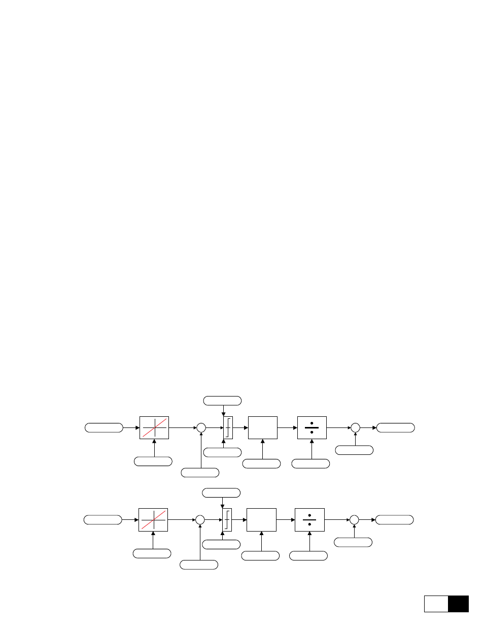
Figure 6.15.4.1: Structure of the signal adaptation