3 power section, Table 4.3.1: terminals description – GE Industrial Solutions DV-300 DC Drive Users Manual User Manual
Page 46
GEI-100332Ga
——— WIRING PROCEDURES ———
4
2
4.3 pOWER SECTION
n
ote
!
Use copper conductors only.
For UL listed equipments use 75°C stranded copper conductors only.
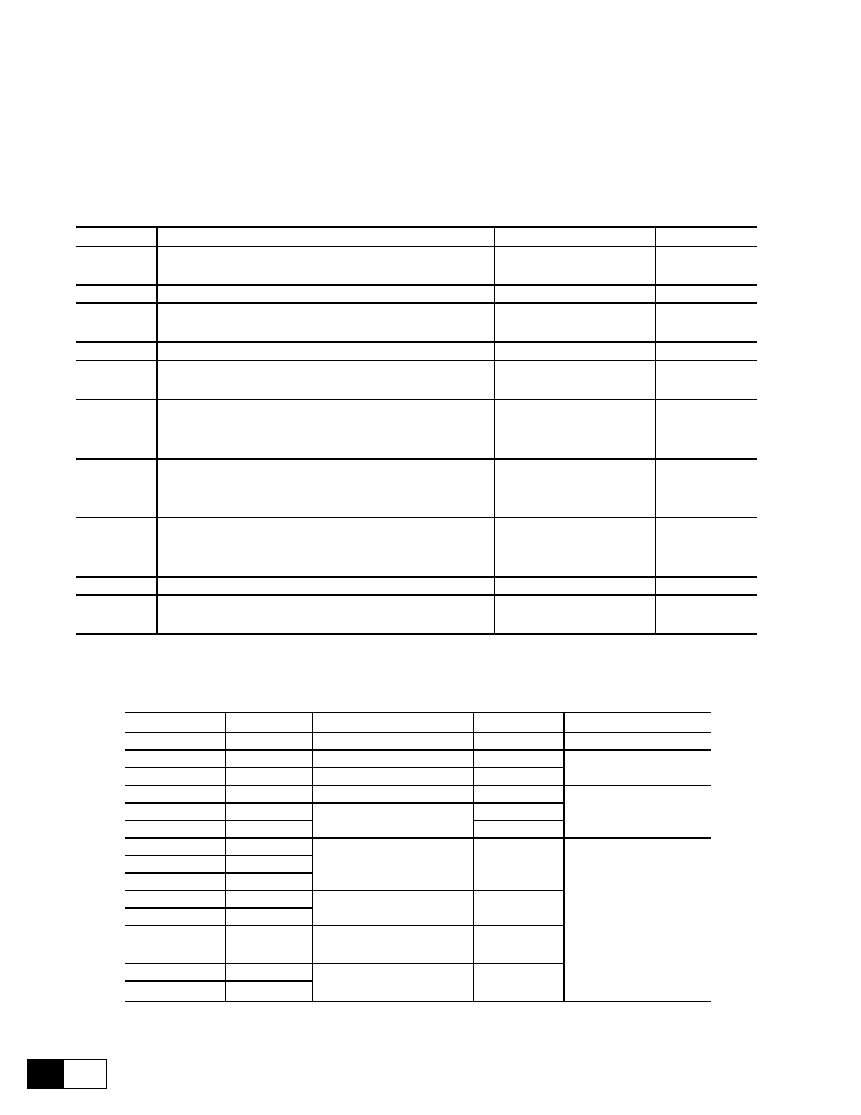
Table 4.3.1: Terminals description
Designation
Function
I/O
max voltage
max current
U, V, W
Connection to the AC mains of the armature circuit
I
500V
AC +10%, 3Ph
see 2.4.2
C, D
Armature connection
O
see 00
see 2.4.3
U1, V1
Connection to the AC mains of the field circuit
I
460V
AC + 15%, 1Ph
see 2.4.2
C1, D1
Field connection
O
0.87 x AC line volts
see 2.4.3
U2, V2
AC power supply regulation
I
115V -10%, 1Ph
230V +10%, 1Ph
see 2.4.2
U3, V3
AC mains power supply for internal fan
(for types with armature current = 560A American)
(for types with armature current = 770A European)
I
230V
AC, 1Ph
1A
35 / 36
Contact without potential of OK relay (closed = OK),
function as per the OK relay func parameter
in the CONFIGURATION / digital output menu
O
250 VAC
1 A AC11
75 / 76
Contact without potential of relay 2,
function as per Relay 2 parameter in the
I/O CONFIGURATION / digital outputs menu
O
250 VAC
1 A AC11
78 / 79
Thermistor connection
I
—
—
81 / 82
Internal fuses intervention signalling
(sizes ≥ 6KDV3560.../6KDV3770...)
O
250 VAC
1 A AC11
GD0110g
Table 4.3.2: Cable size for power terminals U, V, W, C, D, PE
American
European
max cable section [mm2]
AWG
Tightening torque [Nm]
6KDV3017...
6KDV3020...
...4
...12
2...3
6KDV3035...
6KDV3040...
...10
...8
2.5...3
6KDV3056...
6KDV3070...
...16
...6
6KDV3088...
6KDV3110...
6...50
10...1
12
6KDV3112...
6KDV3140...
16...95
6...000
6KDV3148...
6KDV3185...
6KDV3224...
6KDV3280...
Cu-Band 10 x 16 x 0.8
20...25
6KDV3280...
6KDV3350...
6KDV3336...
6KDV3420...
6KDV3400...
6KDV3500...
Cu-Band 11 x 21 x 1
6KDV3450...
6KDV3650...
6KDV3560...
6KDV3770...
Cu-Band 50 x 8 or
2x Cu-Band 10 x 16 x 0.8
6KDV3800...
6KDV310H
Cu-Band 50 x 8 or
2x Cu-Band 11 x 21 x 1
6KDV3850
GD0120g