6 ramp, Figure 6.6.1 : ramp circuit – GE Industrial Solutions DV-300 DC Drive Users Manual User Manual
Page 154
GEI-100332Ga
——— FUNCTION DESCRIPTION ———
6
26
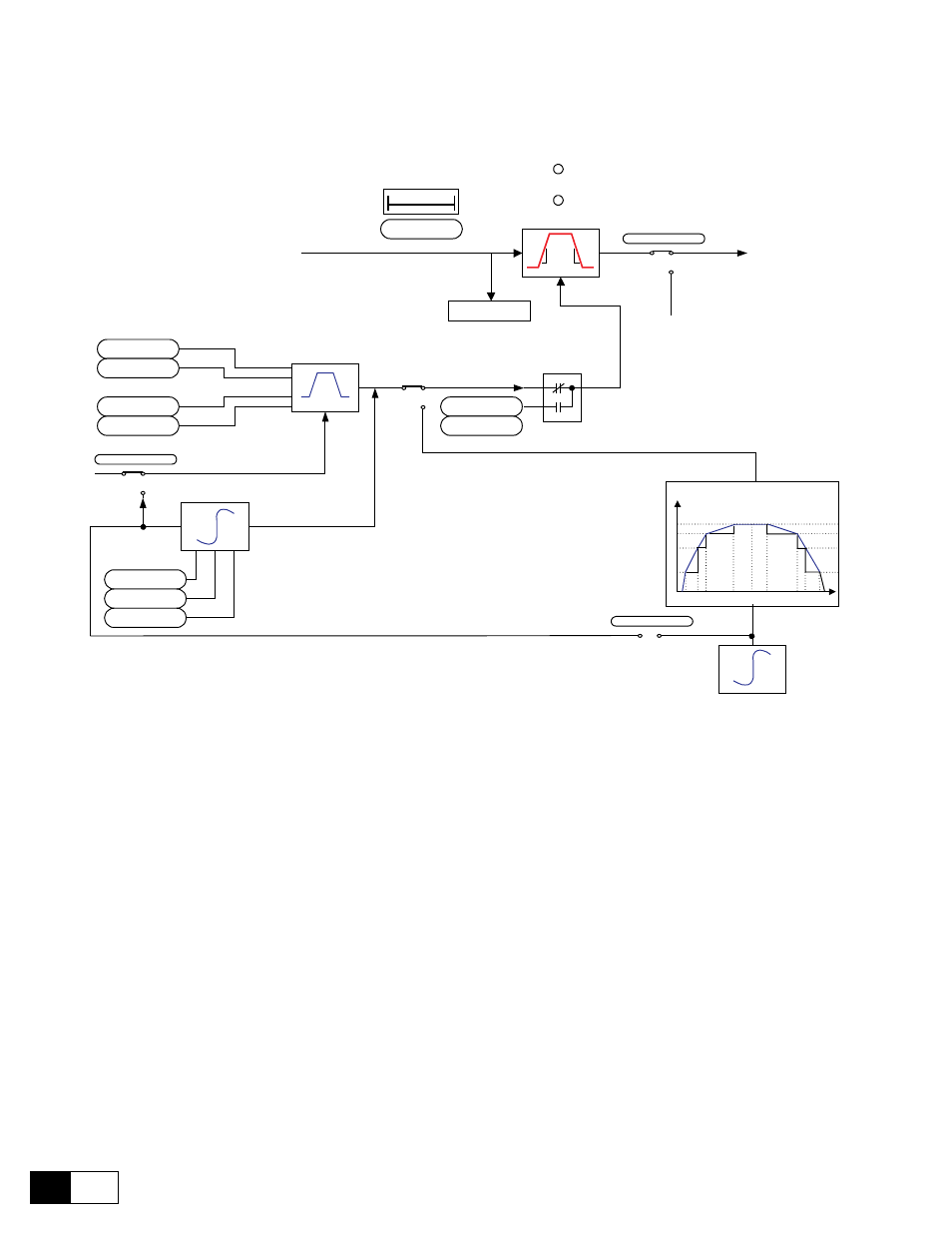
6.6 RAMp
Quick stop
F
Ramp Reference
F
Linear
S-shape
T
Freeze ramp
COMMAND
From
Ramp in = 0
To Speed Reference
generation
Multi Ramp Function
Speed
t
S-shape
T
0
t
Linear
Acc. delta speed
100 rpm
Dec. delta speed
100 rpm
Acc. delta time
1 s
Dec delta time
1 s
QStp delta speed
1000 rpm
Enab multi rmp
QStp delta time
1 s
Ramp +/- delay
100 ms
Ramp ref (d)
Ramp shape
S shape t const
300 ms
S acc t const
300 ms
S dec t const
300 ms
Ramp +
Ramp -
Freeze ramp
Ramp shape
Figure 6.6.1 : Ramp circuit
The ramp (reference value integrator) determines the acceleration and deceleration times of the drive. These
times can be set independently of each other.
An additional ramp is provided for a quick stop. This ramp can only be activated via the serial interface or a field
bus.
The ramp can either be linear or S-shaped..
The reference values can be defined in different ways
- with the Ramp ref 1 and/or Ramp ref 2 reference values
- with the multi-speed function
- with the motor potentiometer function
- with the Jog function
The Ramp generator can be used in a stand alone configuration. When the Ramp generator is disabled (Enable
ramp = disabled), the Enable drive, Start/Stop and Fast stop commands have no more influence on Ramp
generator. In such a condition it is free to run and can be used separately.