5 proportional - integral block, Figure 6.16.3.3: pi block description – GE Industrial Solutions DV-300 DC Drive Users Manual User Manual
Page 271
DV-300 Adjustable Speed Drives
——— FUNCTION DESCRIPTION ———
6
143
Connection to a load cell with full range + 10V.
The output of the load cell can be connected to one of the drive analog inputs. Normally the analog input 1
(terminals 1 and 2) should be used because of the filter provided.
The input choosen for the connection must be programmed in the menu I/O CONFIG as PID feed - back. Its
value can be read in the PID feed - back parameter of the PID REFERENCE submenu.
The tension setting can be sent, with value 0...-10V, to one of the remaining programmable analog inputs in the
I/O CONFIG menu as PID offset 0.
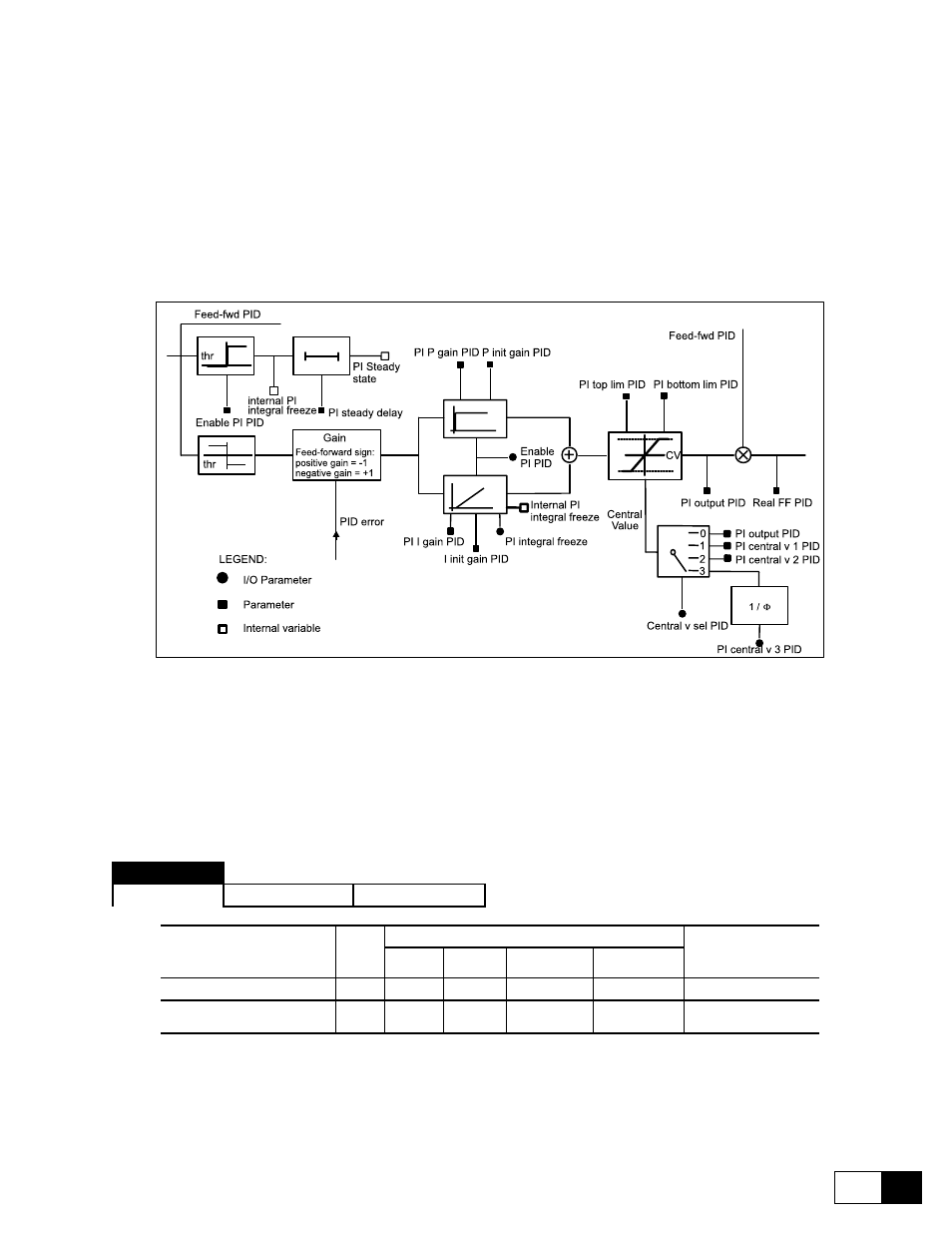
6.16.3.5 proportional - integral block
Figure 6.16.3.3: PI block description
The PI block receives its input from the PID error parameter, which represents the error that must be corrected
by the regulator. The PI block carries on a proportional-integral regulation, its output PI output PID after having
been appropriately adapted, according to the system which it has to control, it will be used as multiplier factor of
the feed-forward (Feed-fwd PID) obtaining the correct value of the speed reference for the drive (Real FF PID).
The PI block will be enabled setting Enable PI PID = Enable. If Enable PI PID has been programmed on a
digital input, this must be set to a high logic level (+2V.
PID
[769]
Enable PI PID
Parameter description
No.
Value
Standard
Configuration
min
max
Factory
American
Factory
European
Menu
Enable PI PID
Enabled (1) / Disabled (0)
769
0
1
Disable
Disable
*
* This function can be set on a digital programmable input.
Enable PI PID
Enabled
Enable of the proportional-integral block
Disabled
Disabling of the proportional-integral blc.