GE Industrial Solutions DV-300 DC Drive Users Manual User Manual
Page 186
GEI-100332Ga
——— FUNCTION DESCRIPTION ———
6
58
[386]
Activity
[387]
Ok relay open
Enable seq err
[728]
Activity
[729]
Latch
[730]
Ok relay open
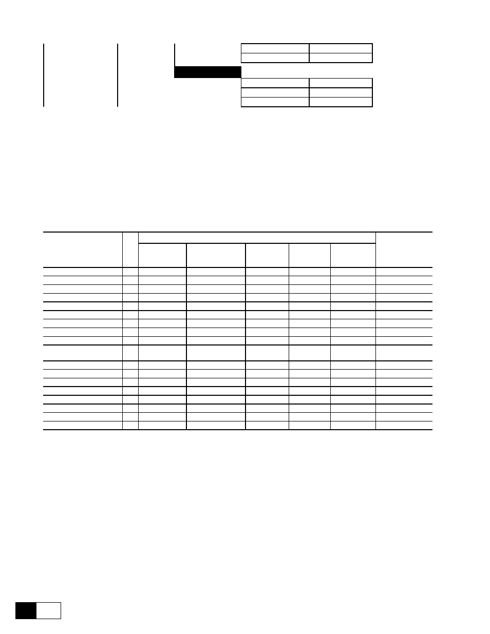
The converters of the DV-300series contain extensive monitoring functions. The effect of possible alarms on the
behaviour of the drive are defined in the PROG ALARMS submenu:
- Saving of alarm status
- How the drive is to react to the alarm
- Indication via the relay between terminal 35 and 36 (central alarm). The switch conditions for the relay can
be defined with the Ok relay func parameter in the CONFIGURATION menu.
- Automatic restart
- Failure reset
For some alarms, the behaviour of the drive can be configured separately. All alarms can also be assigned to a
freely programmable digital output.
Alarm
N.
Factory
Standard
Activity
Latch
Open
OK relay
Hold off
time [ms]
Restart
time [ms]
Failure Supply
Disable drive
ON
ON
-
-
-
Undervoltage
Disable drive
ON
ON
0
1000
Dig. Outp. 7*
Overvoltage
Ignore
ON
ON
0
0
Dig. Outp. 6*
Overspeed
Ignore
ON
ON
0
0
Heatsink
Disable drive
-
ON
-
-
*
Overtemp motor
Disable drive
-
ON
-
-
*
External fault
Disable drive
ON
ON
0
0
*
Brake fault
Disable drive
-
ON
-
-
-
Motor I2t ovrld
Disable drive
ON
ON
-
-
-
Drive I2t ovrld
Disable drive
ON
not programmable
ON
-
-
-
Overcurrent
Ignore
ON
ON
0
0
Dig. Outp. 8*
Field loss
Disable drive
ON
ON
0
0
*
Delta frequency
Ignore
ON
ON
0
0
Speed fbk loss
Disable drive
-
ON
8
-
*
Opt 2 failure
Disable drive
ON
ON
-
-
*
Bus loss
Disable drive
ON
ON
0
0
*
Hw Opt 1 failure
Disable drive
-
ON
-
-
*
Enable seq err
Disable drive
ON
ON
-
-
GD6160g
* This function can be assigned to one of the programmable digital outputs.
If the serial interface or a bus system is used, the alarms can be evaluated via the Malfunction Code parameter.
The parameters required to configure the alarm are shown in Table in Section 10 of the manual.
Activity
Warning
The alarm does not cause reaction of the drive. A warning mes-
sage can be output via a digital output. When the drive is dis-
abled, it will not restart until the failure has been canceled.
Disable drive
The alarm causes the immediate disabling of the converter. The
motor runs to an uncontrolled stop.
Quick stop
When the alarm occurs, the drive stops according to the ramp set in
the RAMP / QUICK STOP menu. The converter is then disabled.
Normal stop
When the alarm occurs, the drive stops according to the ramp
set. The converter is then disabled.
Curr lim stop
When the alarm occurs, the converter brakes with the maximum