Figure 6.16.3.11: diameter calculation – GE Industrial Solutions DV-300 DC Drive Users Manual User Manual
Page 293
DV-300 Adjustable Speed Drives
——— FUNCTION DESCRIPTION ———
6
165
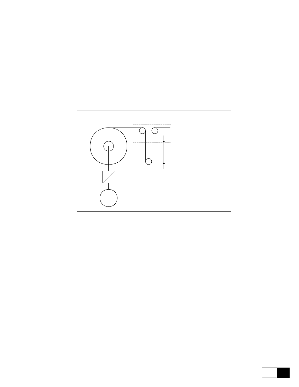
Set Max deviation at a value slightly lower than the one correspondent to the position of max. mechanical seal-
ing allowed by the dancer.
During commissioning, it is always necessary to carry out the self calibration of the analog inputs of the drive.
In particular the one regarding analog input 1, with dancer in its position of lower fullrange, This position is
automatically assigned to the value 10000. So in order to guarantee a precise calculation it might be assigned:
Max deviation = 8000 (Default value)
Set Gear box ratio equal to the reduction ratio between the motor and the winder/unwinder:
Gear box ratio = 0.5
Set Dancer constant to the value in mm correspondent to the total accumulation of material in the dancer:
Dancer constant = (
DL x x
2) 2
= (160 x 2) x 2 = 640mm
M
Gear box ratio
DL = 160mm
WInder/Unwinder
Dancer
DL
Electrical 0
Central position
of working
One pitch dancer
Upper limit
switch = +1000 count
Lower limit
switch = -1000 count
Figure 6.16.3.11: Diameter calculation
Measure of Dancer constant:
Set the keypad of the drive on the parameter PID feed-back.
Measure and multiply by 2, the distance between the lower mechanical fullrange and the position of the dancer
so that in the parameter PID feed-back will display 0 (position of 0 electric).
As the dancer has only one pitch, multiply the above calculated value by 2.
In this case set:
Dancer constant = 640mm
Programm Minimum diameter equal to the minimum value of the core diameter [cm]:
Minimum diameter = 10cm