Figure 6.12.1.1: option card, analog output blocks – GE Industrial Solutions DV-300 DC Drive Users Manual User Manual
Page 194
GEI-100332Ga
——— FUNCTION DESCRIPTION ———
6
66
OFF
Speed ref 1
1)
Speed ref 2
1)
Ramp ref 1
1)
Ramp ref 2
1)
Ramp ref
1)
Speed ref
1)
Ramp out
1)
Actual speed
1)
T current ref 1
2)
T current ref 2
2)
T current ref
2)
Speed reg out
2)
0
1
2
3
4
5
6
7
8
9
10
11
15
Motor current
2)
Output voltage
3)
Analog input 1
4)
Analog input 2
4)
Analog input 3
4)
Flux current
5)
Pad 0
6)
Pad 1
6)
Pad 4
6)
Pad 5
6)
Flux reference
7)
Pad 6
6)
PID output
8)
16
20
24
25
26
27
31
32
33
34
35
38
39
Out vlt level
3)
Flux current max
5)
F act spd
1)
F T curr
2)
Speed draw out
9)
Output power
10)
Roll diameter
Act tension ref
Torque current
W reference
Actual comp
Brake current
11)
79
80
81
82
84
88
89
90
91
92
93
94
Scale output XX
Scaling of the analog output concerned
1)
With a scaling factor of 1 the output supplies 10 V when the reference value or
speed corresponds to the value defined by Speed base value.
2)
With a scaling factor of 1, the analog output = 10V when the reference or current
is 100%.
3)
With a scaling factor of 1 the output supplies 10V when the voltage corresponds
to the Volt value defined via Max out voltage.
4)
With a scaling factor of 1 the output supplies 10V when the voltage reaches 10V on
the analog input (with scaling factor and Tune value of the input= 1). See figure
6.12.2.1.
5)
With a scaling factor of 1 the output supplies 10V when the field current corresponds
to Nom flux curr.
6)
With a scaling factor of 1 the output supplies 10V when a Pad value corresponds
to 2047.
7)
With a scaling factor of 1 the output supplies 10V when the field current reference cor-
responds to Nom flux curr.
8)
For the max. full-scale values, refer to paragraph 6.16.3 PID function
9)
With a scaling factor of 1 the output is 10V when the Speed ratio = 20000.
10)
With a scale factor equal to 1, the output supplies 5 volts to the rated power given
by: Full load current * Max out voltage
11)
output that monitors the value of the Torque proving parameter.
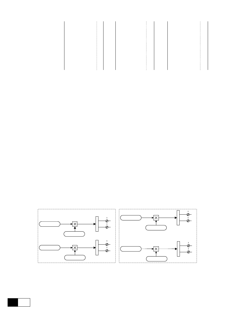
2
1
D
A
C
1
4
3
D
A
C
2
AO1
ACOM
AO2
ACOM
2
1
D
A
C
1
AO3
ACOM
4
3
D
A
C
2
AO4
ACOM
TBO integrated (pos."A")
TBO card pos. B (option)
Select output 1
Actual spd (rpm)
Select output 2
Motor current
Scale output 1
1
Scale output 2
1
Select output 3
Flux current
Scale output 3
1
Select output 4
Output voltage
Scale output 4
1
Figure 6.12.1.1: Option card, analog output blocks
You have at your disposal an analog display device for indicating the speed of the drive. The instrument has
a measuring range of 0 ... 2 V.